9

As you might know, it is hard to get components these days. That's why we engineers have to get creative sometimes ;-)

The company I'm working for has a shortage of a Zener-type voltage reference which comes in a SO8 package. We have found about 3'000 pcs. of the same voltage reference, but in a DIL8 package. The application is a precision measurement device (I'm sorry for not being able to give you more details on the PCB and the IC). We plan to use all 3k DIL8 references.

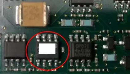
Original Voltage Reference in SO8 package

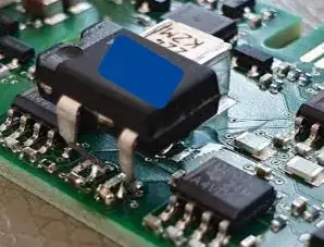
So we need to bend the DIL8 legs with a custom made tool and solder the DIL8 packages on the SO8 footprint (only 3 legs are used/connected)

DIL8 voltage reference on SO8 footprint

Of course this looks very ugly, but an ugly look should not disqualify a technical solution, right?

We passed the following tests:

  • Measurement performance (with the usual humidity and temp profiles)
  • Vibration tests (X/Y/Z, shock 70g/6ms, vibration sweep 3g 10Hz-2kHz, vibration noise)
  • EMC immunity

My questions:

  • What are the possible failure modes of this unconventional soldering?
  • Would you use additional hot glue for fixation (despite the positive vibration tests?)

Any additional thoughts and ideas are welcome. Thanks!
Stefan Wyss
  • 6,471
  • 1
  • 11
  • 22
  • @StefenWyss: Shouldn't be a problem, we rolled out a couple of thousand units with such a hack and they passed through everything -- Compliance, high/low temperature test, drop tests, vibration tests. We used fixation just to be on the safer side, but it wasn't hot glue, we used the white fixation solution that are used by laptop manufacturers. They offered a better performance at high temperatures. – WedaPashi Jun 28 '22 at 06:10
  • @WedaPashi Thanks a lot for your comment. The white fixation solution seems interesting. Can you be a bit more specific on what type of fixation that is? – Stefan Wyss Jun 28 '22 at 06:14
  • Can't you find a SOT23 version instead? It's a common package for zener voltage ref. Much easier to patch in a way that might look semi-professional. – Lundin Jun 28 '22 at 06:30
  • Yet another option: solder two 1x4 1,27mm SMD socket strips where the SO8 is, then solder the upper "connector side" of them to another custom PCB, which also contains the DIL footprint. More expensive but much more rugged. However, it might be overkill - it all depends on what environment the product is sitting in. – Lundin Jun 28 '22 at 06:40
  • @Lundin Very good comment, thank you! I think we have a problem with the height, but I will check that. – Stefan Wyss Jun 28 '22 at 09:09
  • @StefanWyss: We used the sealant from [Silco](https://www.silco-inc.com/neutral-cure), neutral cure, there are also some options by Gree. You need to be looking at neutral cure silicone rubber fixating pastes. However, what Lundin suggested is also a good option to try-out, if space permits. – WedaPashi Jun 28 '22 at 09:37
  • The REF102 is not a Zener-type reference. The REF5010 appears to be pin-compatible (for those three pins), and about 2700 are available at TI. – CL. Jun 28 '22 at 11:04
  • @CL. This is not a REF102 – Stefan Wyss Jun 28 '22 at 16:45
  • I think that hiding the part number makes this off-topic here, because as far as we know, it's an XY problem: you claim that you only got one solution to your problem. That's rarely the case. Even assuming you truly cannot substitute a different surface mount reference (with layout changes), it shouldn't be a big deal to tweak the board layout to accept a DIP-8. Given how much space you seem to have available, that should be the easiest and most robust way to go. Fit the SO-8 pinout within the DIP-8 footprint, rotated 90 degrees (BTDT). The reference looks like an LTC part. – Kuba hasn't forgotten Monica Jun 29 '22 at 00:44
  • @Kubahasn'tforgottenMonica: I was not asking for alternative solutions. My question was related to possible failure modes of the proposed solution. Yes, the reference is a Linear Technology part. – Stefan Wyss Jun 29 '22 at 07:54

2 Answers2

7

Aliexpress sells these:

enter image description here

While it looks more professional than bent legs, it also looks quite cumbersome to manufacture. The SMD connector, which looks like a standard 1.27mm pin header, is soldered with its pins flush to the top of the board. That probably means it was mounted in a jig, then hand soldered to the board. So, difficult to manufacture in a pinch... and the delivery times from aliexpress are quite long...

Another idea would be to manufacture a panel of these, but with a SMD female connector on the bottom and the chip on top. Then, replace the chip on your board with a male SMD connector using the same footprint. However, now you get connector reliability issues.

This would need to be hand soldered to your board, and the chip hand soldered on top. I'm not convinced it'll be cheaper than your current solution.

It's pretty tall, and heavier than a chip, so how will it handle vibration and shock, I wonder...

bobflux
  • 70,433
  • 3
  • 83
  • 203
  • 1
    These particular pieces are kind of ridiculously tall though. I'd pick a socket such as these https://suddendocs.samtec.com/prints/clp-1xx-xx-xxx-d-xx-mkt.pdf Mated height some ~2.2mm. – Lundin Jun 28 '22 at 14:20
  • 1
    Yes it's so tall it looks like it won't like vibration that much – bobflux Jun 28 '22 at 14:27
  • 1
    Given how easy it is to tweak a PCB design these days, any suggestion of using such hacks is IMHO absurd. There is no situation when using an adapter will be lower risk and lower compliance burden than making the board take the actual part you want to use. Any sort of a kludge will cost more in QA, QC, field service/returns, etc. There's no IPC standard for this stuff, so you'd need to write a detailed acceptance document and have the production people develop their process to install those reliably. It's such a mess that it's not even worth speaking of. – Kuba hasn't forgotten Monica Jun 29 '22 at 00:41
5

Converting my comment to an answer: maybe it would be possible to create a SO8 to DIL8/DIP8 converter PCB. Along the lines of this adapter: https://sparkoslabs.com/discrete-op-amps/soic-to-dip-adapter/ (maybe you can use that exact part even?)

One option is to solder two 1x4 1,27mm SMD socket strips where the SO8 is. Meaning that the strips will be where the body of the SO8 would have been.

Then make a custom little PCB with 8 plated vias for the "connector side" of the socket strips and solder that PCB on top of the strips. The footprint layout for these will be length 1,27mm x 4 = 5.08, width = 3.95mm (body width of a SO8).

Outside of these two rows with 1,27mm x 4, make another footprint with plated vias for a standard DIL8, which should be length 2,54mm x 4 = 10,16mm, width = 6.5mm.

I think these two footprints should be able to overlap. Having the DIL IC body resting on the solder joints of the cut socket strips shouldn't be an issue. Otherwise, maybe check what 1,27mm board to board connectors there are on the market.

This solution might be more stable mechanically. Maybe it would even be possible to solder the socket strips to the main PCB using the placement machine instead of hand soldering - I'd check this with the contractor.

Lundin
  • 17,577
  • 1
  • 24
  • 67