0

Follow up to the follow-up question. I am close to my goal to be able to restore the sound circuitry of the arcade game in question. One of my plans was to emulate the comparator circuitry with transistors hoping to get a functional comparator.

I am using the schematics taken from this TI presentation (interesting).

Schematics:

enter image description here

Emulated circuitry (using Microcap 12; .cir file):

enter image description here

I cannot get to change the output by changing the V3 voltage from being greater and lower than V2. The current limiter circuitry has the correct values and I reviewed the schematics multiple times. I am using this also to understand, more in general, how a comparator works since all literature is more complex than the hands-on approach: apply two voltages, and measure the voltage around.

Paperino
  • 205
  • 1
  • 7
  • What happens on the Q1/4 emitters when you change input voltages? What happens on Q2/3 collectors? Trace the signal through from the input a stage at a time. Or what happens when you ground Q7 collector? Try jamming a signal into the output a stage at a time. – Neil_UK Jun 18 '22 at 18:13
  • It should work. Try probing the currents to ensure those 'limiters' are doing what you think. Probe the voltages. Maybe give the transistors some part numbers. Eg. [LTspice](https://i.imgur.com/NE0JA9r.png) – Spehro Pefhany Jun 18 '22 at 18:16
  • Boxes 1&2 are basically a standard differential amplifier stage. They're upside down though, compared to the usual way of looking at them (eg figure Figure 3 in the wikipedia page "Differential" amplifier) as they're built out of PNPs. Box 2 is the current mirror, Box 1 is the main input stage (there are double the transistors as it's a Darlington arrangement: using two transistors to make one "mega transistor"). At the top is your current source. – Dan Sheppard Jun 18 '22 at 18:57
  • Is the end goal to actually build an equivalent using discretes? – jonk Jun 18 '22 at 20:24
  • @jonk in a sense yes. End goal is to add support for it in MAME: https://github.com/mamedev/discrete – Paperino Jun 18 '22 at 21:48
  • @Paperino So emulation, not construction. Got it. Thanks! – jonk Jun 18 '22 at 22:10
  • @Paperino You probably don't have to deal with die temperature variations. That really helps. – jonk Jun 19 '22 at 00:56

2 Answers2

3

I haven't used Microcap very much but I believe X1-X4 are current limiters.

Those should be constant current sources set at the currents seen in the original schematic, although I'm not sure if those are correct, the TI datasheet shows different values. The symbol should be a circle with an arrow in it. Mind you that the schematics given for integrated circuits are often simplified versions of what's actually in the IC, so you may have to use a bit of artistic license when duplicating them.

Current limiters are the wrong thing to use. Try changing them to sources and it should work.

The ST datasheet has a different schematic than the TI one, TI shows one current source for the differential amplifier with the input transistors getting their emitter current from that through diodes. ST shows the diodes, but each input transistor has it's own current source. The TI one is labeled as a "Functional Block Diagram" and probably has just left the extra sources out of the drawing.

enter image description here

Simulating in Microcap, this circuit appears to work better. The TI circuit doesn't transition from one state to the other as quickly, setting the inverting input at 2.0 V, I get the following:

  • +Input 2.01 V - Output = 0.228 V
  • +Input 2.02 V - Output = 1.969 V
  • +Input 2.03 V - Output = 8.318 V
  • +Input 2.04 V - Output = 15.0 V

So you see the output has around a 0.03 V range where the output is somewhere in between high and low.

With the circuit from ST I get:

  • +Input 1.99V - Output = 0.188V
  • +Input 2.00V - Output = 15.0V

With this one a change of 0.01 V or less is needed to fully switch the output.

GodJihyo
  • 17,628
  • 1
  • 16
  • 45
  • Thanks, I will try with current sources vs limiting. I would expect though, that artistic part aside, in a simulation with everything being ideal... it should just work. – Paperino Jun 18 '22 at 20:04
  • @Paperino Please note the additional information in my answer in regards to the schematics. – GodJihyo Jun 19 '22 at 07:05
3

As I understand your purposes (and I'm not sure I entirely do) the schematic found at TI for the LM139-MIL is what you may want to try for MAME purposes. It's nice and simple:

enter image description here

Try using this model below that follows closely with TI's behavioral model above.

Q1 V- IN+ N002 0 QP
Q2 V- IN- N003 0 QP
Q3 N006 N002 N001 0 QP
Q4 N007 N003 N001 0 QP
Q5 N007 N006 V- 0 QN
Q6 N006 N006 V- 0 QN
Q7 DRV N007 V- 0 QN
Q8 OUT DRV V- 0 QN
D1 N001 N002 DX
D2 N001 N003 DX
D3 IN- N003 DY
D4 IN+ N002 DY
I1 V+ N001 80µ load
I2 V+ DRV 80µ load
C1 V+ DRV 1p5
.MODEL QP PNP(IS=1E-16 BF=60 Cje=1p Cjc=300f Rb=300 Re=10 Rc=10 subs=2 Tf=10n)
.MODEL QN NPN(IS=1E-16 BF=200 Cje=1p5 Cjc=500f Rb=100 Re=10 Rc=10)
.MODEL DX D(IS=1.4E-17 Cjo=1p5)
.MODEL DY D(IS=2E-18 Cjo=1p5)

The drawing of the above netlist looks like this:

enter image description here

\$D_1\$ and \$D_2\$ apportion about the right amount of current away from \$I_1\$, per the behavioral model's spec.

If I wrap the above up into a SUBCKT, like this:

.SUBCKT LM139MIL IN+ IN- V+ V- OUT
Q1 V- IN+ N002 0 QP
Q2 V- IN- N003 0 QP
Q3 N006 N002 N001 0 QP
Q4 N007 N003 N001 0 QP
Q5 N007 N006 V- 0 QN
Q6 N006 N006 V- 0 QN
Q7 DRV N007 V- 0 QN
Q8 OUT DRV V- 0 QN
D1 N001 N002 DX
D2 N001 N003 DX
D3 IN- N003 DY
D4 IN+ N002 DY
I1 V+ N001 80µ load
I2 V+ DRV 80µ load
C1 V+ DRV 1p5
.MODEL QP PNP(IS=1E-16 BF=60 Cje=1p Cjc=300f Rb=300 Re=10 Rc=10 subs=2 Tf=10n)
.MODEL QN NPN(IS=1E-16 BF=200 Cje=1p5 Cjc=500f Rb=100 Re=10 Rc=10)
.MODEL DX D(IS=1.4E-17 Cjo=1p5)
.MODEL DY D(IS=2E-18 Cjo=1p5)
.ENDS

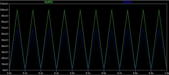
And just use LTspice's opamp2 symbol, for convenience, then I can generate the following test schematic:

enter image description here

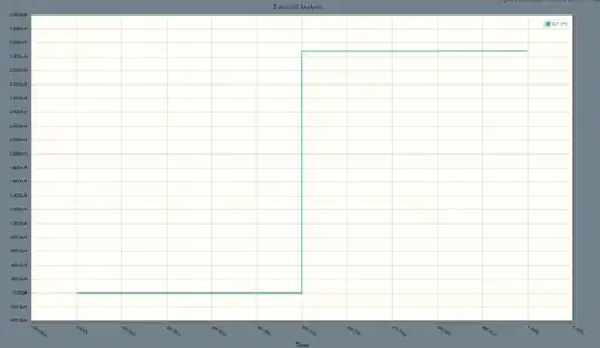
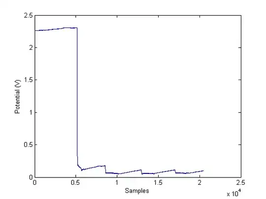
Which should exhibit a comparator with hysteresis (bands set to bracket about \$\frac13\$ and \$\frac23\$ of the supply rail.) Let's have a look at the output:

enter image description here

I think that's working okay. At least for its first test. I haven't put it to much pacing. But for just copying along TI's diagram, it is promising that it hits one high point, at least.

I don't know much about MAME. But from what little I've read today, I suspect this may be sufficient for the needs.

jonk
  • 77,059
  • 6
  • 73
  • 185
  • Thank you. The original schematic from the company who built the game uses and LM339 but the MAME netlist library doesn't support it. So I was going with breaking the IC down to either add it to the library or to the specific game driver. Thank you very much. – Paperino Jun 19 '22 at 23:11
  • @Paperino Let me know if for some reason the above has problems. I think it will be just fine. (The newer datasheet for the LM139/LM239/LM339 uses the 80 uA and NOT the 100 uA current sources, by the way. I didn't reference it above because I had not yet seen it. But now I have.) I carefully tinkered D1 and D2 for this circuit. I think things should be just fine. – jonk Jun 20 '22 at 00:30