Note: The question part is the fixing of the negative current at the transistor base. It looks like there's a problem with negative current at the LED(s) -- this is not expected to be answered in this question, but will be a separate question, if needed. Finally, I asked for comments, because I want to know what others think about this circuit, but again, it is not really part of this question. (If you feel like fixing the LED problem or commenting, please do, but that will have nothing to do with acceptance of a particular answer). I just said all of that to try to avoid a "too broad" disqualification.
I found this interesting alternative Joule Thief, which the creator named the "Super Efficient Joule Thief". I thought up a name for this. Would a good name for this be the Half-Hartley Joule Thief? A comment in the link calls it a modified Colpitts, but I think it's closer to a Hartley.
This particular Joule Thief alternative is interesting because it is a resonant type I haven't seen before. It is also interesting to me because the inductors are not coupled, making it easier to throw together with a few scrounged inductors, meaning that you don't have to wind your own traditional Joule Thief coupled inductor.
Here is the original schematic from the designer (he uses 4 of the same kind of 82uH axial inductor, probably not terribly efficient.):
In the pictorial schematic above, the diodes are backwards and make a short-circuit, as astutely observed by one commenter. Also, the schematic circuit diagram above has the diodes in correctly, but in the video, that schematic is wrong, so be wary.
In my first schematic, I removed the diodes because they didn't seem to do anything:
Then I modified the circuit a bit, mainly combining the three serial inductors into one, but also selecting real inductors.
Almost all of the Joule Thief alternatives have reverse base current, so is there a way we can solve this? Or how I can know how much is too much?
The schematic of my version of the "Super Efficient Joule Thief" (attribution included):
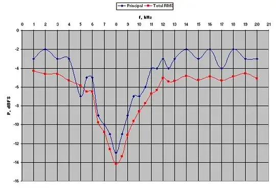
Here is a picture of the resonant behavior (Isn't it beautiful! Except for the hiccough, of course!):
Some traces showing reverse base current, and also voltage traces on the base and on the collector of N1 (per request in comments):
Here are some calculated values taken from 0ms to 8ms:
Ib(N1) :
- 48.496µA AVG
- 107.24µA RMS
V(N1b)*Ib(N1) :
- 1.0388mW AVG
- 8.3102µJ integral
0.5*(ABS(V(N1b)*Ib(N1))-V(N1b)*Ib(N1))
- 23.751µW AVG
- 190.01nJ integral
Actually, this reverse base current does not seem so bad, but I often have problems with reverse current at the base. I've put my time in. Would you please tell me how to solve this?
Note: I have not yet built this circuit because of the multiple problems -- the base problem, as well as the LED reverse current problem.
Here is the LTspice XVII source code for your convenience:
Version 4
SHEET 1 1420 864
WIRE 64 -48 -48 -48
WIRE 96 -48 64 -48
WIRE 208 -48 176 -48
WIRE 288 -48 208 -48
WIRE 672 -48 288 -48
WIRE 704 -48 672 -48
WIRE 672 -16 672 -48
WIRE 288 0 288 -48
WIRE -48 16 -48 -48
WIRE -48 16 -80 16
WIRE -48 80 -48 16
WIRE 64 80 64 -48
WIRE 96 80 64 80
WIRE 208 80 208 -48
WIRE 208 80 160 80
WIRE 672 96 672 64
WIRE 672 96 464 96
WIRE 704 96 672 96
WIRE 672 160 672 96
WIRE 464 208 464 96
WIRE 112 256 80 256
WIRE 288 256 288 80
WIRE 288 256 192 256
WIRE 368 256 288 256
WIRE 400 256 368 256
WIRE -48 352 -48 160
WIRE 80 352 80 256
WIRE 80 352 -48 352
WIRE 464 352 464 304
WIRE 464 352 80 352
WIRE 672 352 672 224
WIRE 672 352 464 352
WIRE -48 368 -48 352
FLAG -48 368 0
FLAG -80 16 V1
FLAG 704 96 D1
FLAG 368 256 N1b
FLAG 704 -48 L2
SYMBOL voltage -48 64 R0
WINDOW 123 0 0 Left 2
WINDOW 39 0 0 Left 2
WINDOW 3 18 92 Left 2
SYMATTR Value 1.5
SYMATTR InstName V1
SYMBOL res 272 -16 R0
SYMATTR InstName R1
SYMATTR Value 1K
SYMATTR SpiceLine tol=1 pwr=0.1
SYMBOL cap 96 96 R270
WINDOW 0 32 32 VTop 2
WINDOW 3 0 32 VBottom 2
SYMATTR InstName C1
SYMATTR Value 100nF
SYMBOL ind 80 -32 R270
WINDOW 0 32 56 VTop 2
WINDOW 3 5 56 VBottom 2
SYMATTR InstName L1
SYMATTR Value 100µH
SYMATTR SpiceLine Ipk=5 Rser=0.028 Rpar=0 Cpar=0 mfg="Coiltronics" pn="CTX100-5-52"
SYMBOL ind 656 -32 R0
SYMATTR InstName L2
SYMATTR Value 270µH
SYMATTR SpiceLine Ipk=5.2 Rser=0.0688 Rpar=25434 Cpar=0 mfg="Coilcraft" pn="PCV-2-274-05"
SYMBOL LED 688 160 M0
WINDOW 3 -61 76 Left 2
SYMATTR Value LXK2-PW14
SYMATTR InstName D1
SYMBOL npn 400 208 R0
WINDOW 0 62 21 Left 2
WINDOW 3 22 48 Left 2
SYMATTR InstName N1
SYMATTR Value 2SCR553P
SYMBOL res 208 240 R90
WINDOW 0 0 56 VBottom 2
WINDOW 3 32 56 VTop 2
SYMATTR InstName R2
SYMATTR Value 22K
TEXT 120 336 Left 2 !.tran 0 16ms 8ms startup
TEXT -616 184 Left 2 ;orig source before mods:\nSuper Efficient Joule Thief DIY \nby GEORGE CHANIOTAKIS in leds\non "instructables" web site\nhttps://www.instructables.com/id\n/Super-Efficient-Joule-Thief-DIY/
TEXT -680 -24 Left 2 !.meas iD1 AVG I(D1)*1000\n.meas iV1 AVG -I(V1)*1000\n.meas Pin AVG -V(V1)*I(V1)*1000\n.meas Pout AVG V(D1)*I(D1)*1000\n.meas Eff param 100*Pout/Pin
TEXT -712 -24 Right 2 ;92.38 mA\n214.95 mA\n322.4  mW\n285.0  mW\n88.4062 %
TEXT 408 24 Left 6 ;88%
TEXT 592 280 Left 5 ;92 mA
TEXT -1184 -56 Left 2 ;Ib(N1)\n=========\n48.496µA AVG   \n107.24µA RMS\n \nV(N1b)*Ib(N1)\n===========\n1.0388mW AVG\n8.3102µJ integral\n \n0.5*(ABS(V(N1b)*I(R1))-V(N1b)*I(R1))\n=========================\n15.079µW AVG\n120.63nJ integral
RECTANGLE Normal -240 128 -880 -64 2


