1

My home automation infrastructure has an alarm system that is capable of operating a flash and a 12V siren. Our house is equipped with a siren that was used to be operated by an obsolete alarm system which was defunct. I want to connect my new alarm system to the existing siren (which includes a horn and a flash.)

While the obsolete alarm system generated a proper signal for the siren to make some real wailing noise, the new one can only operate the flash and switch on +12V for the horn.

The goal was to create a circuit that gets activated when the 12V is switched on and send some siren wailing to the horn.

After fiddling around with a couple of demo schematics, I implemented the one shown here:

enter image description here

I used a terminal block to easily connect both the horns' +12V and ground line as well as the +12V and ground line from the alarm-system. As you can see, the external power source also powers the Arduino on Vin. The code on the micro-controller is generating a tone that is sent through pin 7 via a 1K resistor to the base of a high power NPN transistor that in return acts as a switch in between the circuits' and the speakers' ground while the speaker's +12V is also connected to the external power source.

The result is overwhelming: The horn outside my house makes some reeeeal loud noise. Because it is like 25 years old, I don't have any specs at my hands but from a quick research, it seems as if it is pulling something like 340mA while generating noise at around 110db.

You may wonder what the question is.

I would like to know if this circuit makes any sense to you and despite that it does seem to work pretty well: Did I miss something? It doesn't seem to generate noticible heat on its components, but I am not sure if there might be a possible high load on the Arduino itself where it must not be.

[UPDATE]

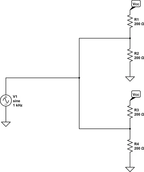
I am not an expert, but this should be the corresponding schematic, as it might be easier to read for some people:

enter image description here

JRE
  • 67,678
  • 8
  • 104
  • 179
Mephisztoe
  • 119
  • 2
  • As your designs get more complicated, you will want to include a schematic instead of a picture/diagram. See https://electronics.stackexchange.com/q/105136/2028. – JYelton May 31 '22 at 21:23
  • 1
    You're right @JYelton. Tried my best and I hope the schematics are correct :) – Mephisztoe May 31 '22 at 22:22
  • You have the Arduino driving the TIP120 NPN darlington with audio square waves then the TIP120 feeds the horn speaker with DC pulses. But a speaker is designed to use AC because with DC it might not sound good and might damage the speaker. You need an AC audio amplifier to replace the darlington. – Audioguru May 31 '22 at 22:26
  • 1
    @Audioguru, the siren is specified to run on 12V DC; it is not a regular speaker. – Mephisztoe May 31 '22 at 23:21
  • 1
    I don't see any issues with your circuit, but I am writing a comment instead of an answer because I'm unsure. If the siren is just a piezo style siren, it probably has its own circuitry to generate the frequency sweep etc. As such you're just turning on and off a load, and a Darlington transistor is OK for that (the TIP120 is very robust). You could also use a MOSFET. Unfortunately "is this design OK" type questions are very hard to provide a definitive answer for. – JYelton May 31 '22 at 23:49
  • @JYelton, you are absolutely right: This kind of question is really kind of hard to provide an answer for. Because I am far from an expert in regards to electronics, I just wanted to make sure that there is no obvious flaw. :) – Mephisztoe Jun 01 '22 at 07:00
  • Your schematic does not say what is the "speaker". Maybe the horn is the 12VDC siren module from Sparkfun? It might produce a siren sounds or warble two frequencies (bee, boo, bee, boo etc) like police cars in Europe. – Audioguru Jun 02 '22 at 18:09
  • Did you reach the goal to make the siren wailing? Or does it produce only one tone? – Ariser Jun 18 '22 at 08:17
  • A reverse viased diode across the speaker to absorb tranients when the transistor turns off may help. OK cct looks OK. – Russell McMahon Jun 19 '22 at 07:25
  • PLEASE provide speaker/siren detail. Part number and link if available. || Does it make a siren sound when 12V is supplied and no Arduino is used? – Russell McMahon Jun 19 '22 at 07:27

1 Answers1

0

The circuit is with one exception rather safe for the Arduino and the Transistor as well.

The Arduino is protected by the collector-base diode of the transistor. If you want to increase safety margins further you can increase the resistor to 2.2 kΩ or even 4.7 kΩ. In the rare case of the transistor failing, the resistor will limit the current from 12V into the Arduino's output to something the internal protection diodes can handle.

The exception: The siren isn't a standalone device but just a speaker. A speaker contains an inductor which can harm the transistor. As long as you don't know better, you should add a power Schottky diode to any unknown load you drive with such a circuit. (Sorry there isn't any symbol for Schottky diodes, so I had to take a p-n-diode)

schematic

simulate this circuit – Schematic created using CircuitLab

It stays unclear if the siren is made for this operating mode. Without a recorded output signal from the old alarm system it's not easy to find out what was intended. Issues might be: The horn was originally driven by some audio amplifier in the old system which reduced the voltage and applied a sine wave or other formed signal. Your signal is a hard square wave which has a powerful spectrum, which might drive the siren out of spec. But that's speculative.

If you want to limit the power output, you can reduce the on-time of the signal relative to the off time in your arduino code. But that includes maybe some more hacking.

Ariser
  • 3,846
  • 3
  • 23
  • 43