0

I am trying to switch either a 12v motor or a relay with the outputs of a LM3915.

I have found an answer on this site about using a pnp transistor on the outputs to switch multiple leds. the circuit - such as this one:

What transistor do I need to drive many LEDs and how should I hook it up?

works for leds but doesnt seem to make a motor spin, the 12v motor or relay just makes a tone.

Is it possible to use this circuit to work with motors or relays?

Any pointers in the right direction much appreciated. Thanks
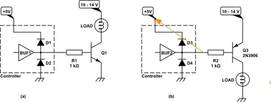
enter image description here

1 Answers1

1

Not exactly

Rules of Thumb for Design

  • BJT switches are optimized with about 10% of hFE max as a saturated switch
  • coils will flyback back EMF voltage need some clamp protection V=LdI/dt. RC, R or R+Diode or Zener + diode.
  • Small relays can use signal diodes rated for 10% of DC current to meet SOA on datasheet with lots of margin
  • Measure Motor DC resistance DCR to define surge current. It will be 10x the full load (rated) current at full speed and 100x the no-load current +/-20%
    • then choose a transistor that can handle this current with margin and not overheat.
    • then choose base current to be 10% of hFE max based on Ohm's Law with worst-case supply tolerances
    • check that PD in transistor does not exceed 50% of max power spec to achieve a 50'C temp rise on the case ( and more inside)
    • It is OK to slightly exceed uC current since VoH is not a logic "1" level.
    • Be sure your supply can handle the 10x surge, otherwise ramp up PWM at some frequency to limit current in x seconds.
Tony Stewart EE75
  • 1
  • 3
  • 54
  • 182