0

Off-the-shelf thyristors are optimized to switch at mains frequency, - 60 Hz in the U.S.A. In my application, I need MHz speeds, 10 to 20 watts, 5 to 10 volts.

Is it possible to emulate thyristor behavior using other components?

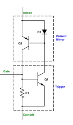
This seems to be a good low-parts-count solution using BJTs, but FET's are preferable. enter image description here https://electronics.stackexchange.com/a/344346/65001

Could it be emulated with MOSFETs? It doesn't have to be MOSFETs.

My application is a thyristor-controlled rectifier with an isolated SMPS. enter image description here https://www.ppi-uk.com/news/thyristor-controlled-rectifiers/

Here's the isolated SMPS i'm trying to current-limit. I want to use a thyristor in place of Dfly. enter image description here

johny why
  • 166
  • 8
  • 1
    You can't make a thyristor out of discrete components. A thyristor is like a BJT or MOSFET: a single hunk of silicon. If anything, the equivalent circuit in your link says a couple of BJTs so I don't know why you are talking about MOSFETs. However, two a piece of P and N doped silicon connected by a wire is not the same as them butted up against each other because there's no junction. – DKNguyen May 21 '22 at 03:13
  • 1
    You want to use thyristors for MHz power conversion??? Not going to happen. MHz power conversion happens in low power integrated silicon DC-DC converters and for higher power with GaN or SiC FETs. – John D May 21 '22 at 03:14
  • 3
    Thyristors are inherently slow, there's no way you can make one run at MHz speeds. And making one out of discrete parts is even more of a recipe for trouble. The problem isn't that they're optimized for low speeds, it's that they're physically limited to speeds below a few dozen kHz at the absolute maximum. – Hearth May 21 '22 at 03:22
  • Making a MHz Phase controlled current source might be possible with a BJT full bridge but makes no sense for current regulation on the AC side for phase control with specs for load and parameters that make sense. define your full specs or delete. – Tony Stewart EE75 May 21 '22 at 03:31
  • @TonyStewartEE75 I've stated speed and power. Added topology. What other info would help you? – johny why May 21 '22 at 04:07
  • 1
    If all you are looking for is a switch that can block AC, then two back-to-back MOSFETs sharing a common source will do it, as well as being able to switch fast. That's basically a type of SSR, but there are multiple ways to make SSRs. The ones that use thyristors won't behave the same way. – DKNguyen May 21 '22 at 04:08
  • What output voltage? How many MHz? What is the expected load? – Bruce Abbott May 21 '22 at 04:08
  • 1
    ""to pass in a graduated manner, by firing (switching on the thyristor) at a precise time, therefore controlling the conduction angle."" If you truly mean passing current in a graduated manner, this will fry your device. No current through + high voltage across (blocking) = no power dissipated. Moderate current through + low voltage across (conducting) = low power dissipated. Moderate current + moderate voltage across (graduated current)= fried device. That's why we really try to only use linear for low power and try to use switching for high power. – DKNguyen May 21 '22 at 04:20
  • @BruceAbbott I've remove stuff about rectifiers and SMPS. Application doesn't matter. The question now is simply, " Is it possible to emulate thyristor behavior at Mhz speeds?" – johny why May 21 '22 at 04:20
  • 1
    Which behaviours of the thyristor are you after? Ability to block current in both directions? Only able to conduct current in one direction? Latching once conducting? – DKNguyen May 21 '22 at 04:21
  • @DKNguyen I may be wrong, but i believe a thyristor IS a switching device, not a linear device. SCR's and Triacs are used to high-current light-dimming applications. – johny why May 21 '22 at 04:21
  • 2
    Yes a thyristor is a switching device only which is why I was confused when you said "graduated". The light is dimmed, but the current isn't actually graduated. More like it's being chopped up rather than throttled (which is what I interpret graduated to mean). – DKNguyen May 21 '22 at 04:22
  • Yes, i believe it's chopped up. The word "graduated" was a quote from the article i linked. – johny why May 21 '22 at 04:25
  • Why do you think you need a thyristor? Why do you think you need thyristor behavior? SCRs and Triacs *were* the 'go-to' option for high current light dimming *in the previous century*, but we're moving on from that because they're not a useful at high frequencies. I strongly suggest you edit your question to describe your application in more detail, *without* presupposing a solution. Perhaps the answer you're looking for is something like 'synchronous rectification', but it's hard to say without more detail. – brhans May 21 '22 at 11:39
  • 2
    Based in the above circuit, it is controlled rectifier. Thyristors still work there. To get more MHzs, it is necessary to build it on non-saturated devices without internal positive feedback, like power HF MOSFET or Schottky-FET, or even BJT, but with anti-saturation circuit. – Vladimir May 21 '22 at 13:32
  • @BruceAbbott Voltage info added, 5-10V. – johny why May 21 '22 at 14:10
  • @Vladimir Please share the schematic :) – johny why May 21 '22 at 15:24
  • "My application is a thyristor-controlled rectifier" - but still, you've already decided that you need thyristors. There's a reason you don't find these operating at MHz frequencies, and that's because there's always a better way of performing the actual underlying function - which you've refused to share ... – brhans May 21 '22 at 18:15
  • After replacing thyristors and diodes with transistors, your controlled rectifier becomes synchronous rectifier. There are many ready-to-use circuits of them in the net. We can answer then some more certain and specific questions, closer to application, i mean. – Vladimir May 21 '22 at 21:35
  • @brhans Current limiting/regulation – johny why May 21 '22 at 23:02
  • Neither of which *needs* a thyristor - so back around we go ... – brhans May 22 '22 at 01:09
  • Also - you can't just slap a full-bridge rectifier (thyristor-controlled or not) on the output of a flyback converter. That's not just a transformer being fed with a high-frequency AC sine wave. – brhans May 22 '22 at 01:19
  • @brhans The converter i'm using is isolated. It already has a rectifier designed into it, Dfly. i want to use a thyristor in place of Dfly. – johny why May 22 '22 at 14:19
  • @johnywhy What's the advantage of using a thyristor there? – Hearth May 22 '22 at 14:31
  • You can't do that to a flyback converter - and particularly not that one which samples the flyback voltage in order to regulate its output. – brhans May 22 '22 at 14:32
  • @Hearth current regulation or limiting – johny why May 22 '22 at 14:59
  • @brhans "one which samples the flyback voltage" - Why? – johny why May 22 '22 at 15:00
  • Flyback converter is a current source by its nature (more precisely, it is power source). Output power is limited by magnetic flux energy, stored in transformer core at each period. If you need more accurate current regulation, then you should measure current (with shunt for example) and feed it back to controller. – Vladimir May 22 '22 at 20:14

3 Answers3

2

Your BJT thyristor will be faster than a bought one. But the need for PNP and NPN will make high power/High voltage not good. One way to make it faster is to employ a baker clamp or similar scheme to prevent hard saturation. This proposed faster device will have a greater forward voltage drop. Lower voltage transistors are usually faster but mean a lower breakdown voltage device. The BJT thyristor can not block any significant reverse voltage which means that if your application needs significant reverse blocking, a series diode is called for increasing voltage drop even more. Finally a mosfet scheme will waste even more volts because gate drive on normal powermos is much more than VBE.

JYelton
  • 32,302
  • 33
  • 134
  • 249
Autistic
  • 14,235
  • 2
  • 27
  • 65
  • Assume the usage is a current-controlled rectifier on the output of an isolated SMPS. Would reverse volts be an issue? – johny why May 21 '22 at 14:18
  • This answer sounds more like "no, you can't do that", rather than "You can do that, and here's a schematic." – johny why May 21 '22 at 15:31
  • I showed it can be done but but not without challenges and unexpected behaviors, so it's an academic solution to a non-problem. Thyristors do not have a Baker Clamp in them or special components with high for GBW speed. They are designed for low frequency commutation with phase control at the lowest cost. SCR's are prone to high dV/dt false triggers if attempted. End-of-story – Tony Stewart EE75 May 22 '22 at 04:46
2

Yes, you can. It will be as fast as the BJTs you use.

You can replace D1 with a resistor.

The choice for the resistors gives a tradeoff between turn-on ease and turn-off delay.

Turn-off is limited by recovery from deep saturation of the 2 BJTs. A Schottky diode or even a Baker clamp could be used, but a) the Schottky diodes would need to be able to carry most of the total current, and b) a Baker clamp would increase the on-voltage.

Note that the BJTs operate with a forced beta of about 1, so they need to have a base current rating of this - this is not commonly specified and may be lower than expected (compared to specified collector current.)

JRE
  • 67,678
  • 8
  • 104
  • 179
jp314
  • 18,395
  • 17
  • 46
  • Is it *necessary* to replace D1 with a resistor. I don't claim to understand this, but the designer used D1 to reduce voltage-drop and power dissipation. "a way to reduce the needed base currents so that the voltage drop across the BE junctions can be similarly reduced. Allow a better division of the SCR current so that more of it flows through the collector of Q1, using a diode." – johny why May 21 '22 at 14:16
  • Would your solution support 10 to 20 W at 5 to 10 V? Can you share a schematic? – johny why May 21 '22 at 14:17
  • Can you share a FET-based solution? – johny why May 21 '22 at 15:31
  • A FET solution will be limited to the max VGS of either FET, and also will have a saturation V of at least VGS. However it is not a good idea as the current MUST flow through the resistors, so trigger and holding current is very high. – jp314 May 21 '22 at 19:45
0

" Is it possible to emulate thyristor behavior at Mhz speeds?

Not likely. But it can make a perfect set only latch.

Maybe with the right transistor geometry in the same package that can dissipate 50% of max rated power and add snubbers for dV/dt which may easily trigger falsely and stay ON.

The facts are a Discrete cannot easily mimic the monolithic SCR. The PNPN junctions is different from the PNP<>NPN as the middle NP junctions will never match in discrete devices and the diode junction capacitance increases at high Amp ratings at V=0.

The base ends up drawing much more than 10% of the load at turn ON instead of what you might expect with hFE reducing down from 100 towards Vce(sat) ratings of 10:1.

Here is a quick simulation.
enter image description here

The BJT pair drops 2V at 0.5A and you must derate the 1W shared dissipation here and cannot use a TO-92.

See below using 24Vp 1MHz with 50 Ohm load.

Another demonstration shows it triggers by itself with 0V input unless Vbe is shunted by 100//220, then once triggered, it won't switch off due to junction capacitance between C-B's.

Note that Vbe rises to 0.9V ( scaled *10)
enter image description here

Then @jp314 reminded of the Baker clamp and I got something working for 1 cycle using two (2) 0.1 uS pulses delayed 30 degrees with the rectified 24V 100W 1MHz power source.

enter image description here

Conclusion

The better solution to this hypothetical problem is to define the loads, voltages and currents and consider a Dual half-bridge IGBT or FETs.

Additional comments

Q1 NPN gets the higher Vbe so PNP Q2 base and diode shares very low power.. That diode doesn't make much difference to guarantee cutoff. The Schottky diodes makes a huge difference. Also the NPN base resistance conducts a great deal of power and must be beefed up accordingly, unlike heavily doped discrete parts with tiny BE junctions.. You may examine the NPN Base current in my simulation it's alot more than the typical 10:1=Ic:Ib and depends on Rbe.

The PNP B-E resistor vs diode argument was considered in my simulation and I found no performance enhancements . But the Baker Clamp to prevent saturation capacitance reocvery times is essential for the discrete attemp.

This design idea is not recommended to attempt except for personal experience. Examine the simulation to save time.
Tony Stewart EE75
  • 1
  • 3
  • 54
  • 182
  • You mentioned voltage drop as a drawback. I don't claim to understand this, but the designer of the schematic i shared used D1 to reduce voltage-drop and power dissipation. "a way to reduce the needed base currents so that the voltage drop across the BE junctions can be similarly reduced. Allow a better division of the SCR current so that more of it flows through the collector of Q1, using a diode." I may be wrong, but i think the R is important to that. I can't tell if you included the R. – johny why May 22 '22 at 15:22
  • 1
    That's a great question. Q1 NPN gets the higher Vbe so PNP Q2 base and diode shares very low power.. That diode doesn't make much difference to guarantee cutoff. The Schottky diodes makes a huge difference. Also the NPN base resistance conducts a great deal of power and must be beefed up accordingly, unlike heavily doped discrete parts with tiny BE junctions.. You may examine the NPN Base current in my simulation – Tony Stewart EE75 May 22 '22 at 15:26
  • "consider a Dual half-bridge IGBT or FETs." Do you mean a driver? I did, but low parts-count is a priority, and the LM25184 was recommended for low-parts. – johny why May 22 '22 at 15:37
  • Thx for simulating this. What's the drawback of the one you got working? – johny why May 22 '22 at 15:39
  • "consider a Dual half-bridge IGBT or FETs." - Do you mean using a driver? – johny why May 22 '22 at 15:41
  • 1
    The last stage switch driver is what I intended as the SCR is a driver . Back in the 70's Lambda used a phase controlled SCR full bridge to make a pre-regulated linear voltage just high enough to cover the drop voltage in the Linear regulators to minimize heat loss. even for 1kW rack supplies. Very high power , reasonable efficiency at extremely low noise. but still not cheap. like today < 10 cents /W even wit hinflation ! – Tony Stewart EE75 May 22 '22 at 15:51