1

I'm looking for the smallest circuit to make some noise. This sound has to be constant and annoying, it's intended for the alarm on a timing device. Any ideas?

The circuit will be triggered with a high line from a microcontroller. Supply voltage can be 5V or 9V.

  • Is this circuit going to be stand alone? Any other circuitry around it, perhaps a microcontroller? What circuitry does the timing device contain, or does it even contain electronics? – abdullah kahraman Mar 22 '13 at 18:10
  • @abdullahkahraman sorry, I added some information to my question. –  Mar 22 '13 at 18:12
  • If you have a pin available on the microcontroller, just drive the speaker or buzzer with it and a transistor? – abdullah kahraman Mar 22 '13 at 18:13
  • @abdullahkahraman possibly, yes, you should make that an answer! –  Mar 22 '13 at 18:14
  • Possible duplicate: http://electronics.stackexchange.com/questions/36461/what-is-the-simplest-sound-generating-circuit – shimofuri Mar 22 '13 at 18:45
  • A 555-based oscillator is trivial to build. – bit-twiddler Mar 22 '13 at 18:22
  • This is an ill-defined question. Do you want the easiest, smallest, cheapest, or most basic (easy to understand) circuit? These are very different criteria! – Wouter van Ooijen Mar 22 '13 at 20:48
  • @WoutervanOoijen I'll change the title, it's misleading indeed. In the question, I ask for 'smallest'. –  Mar 22 '13 at 20:54
  • So you mean physically smallest, the smallest volume? I think that would make the one-transistor piezo oscillator the winner, either built-it-yourself or as piezo-with-electronics. – Wouter van Ooijen Mar 23 '13 at 08:15
  • @WoutervanOoijen he has a port available for this in his microcontroller. – abdullah kahraman Mar 23 '13 at 08:46
  • @WoutervanOoijen I agree, but will wait with accepting it for others to give some ideas as well. –  Mar 23 '13 at 09:30

4 Answers4

6

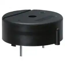
Perhaps the least-effort option that meets the specified requirements is to use a piezoelectric buzzer, such as this one:

Piezoelectric buzzer

They can be had for under US$1 from various sites like eBay.com.

This datasheet lists a number of such buzzers: Stay away from the ones that specify "without circuit" or "external drive type".

A MOSFET or BJT as a switch, driven from the microcontroller GPIO pin, is sufficient to operate the buzzer.

These buzzers come at a wide range of "annoying" sounds, pick one to your liking.

Anindo Ghosh
  • 50,188
  • 8
  • 103
  • 200
4

You could just probably drive a DC buzzer, which Anindo showed, with a transistor using one of your microcontroller's pins.

I have shown an example in the below schematic. Pick the R1 so that it gives enough gain to your transistor.

Since you do not want much components, you can maybe remove pull-down resistor R2 if you can get away with small problems, such as a weak and short beep on power-on, when the microcontroller's pin is floating.

Also, a fly-back diode may not be necessary, depending on the buzzer.

I have happened to pick a PIC16F616, it is an over-kill as Olin notes and I did not pay attention to that. Feel free to use your own microcontroller which you are already using in your design.

enter image description here

abdullah kahraman
  • 5,930
  • 7
  • 59
  • 104
1

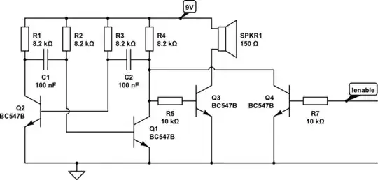
If you are into discrete components, one of the simplest circuits possible is the Astable Multivibrator:

schematic

simulate this circuit – Schematic created using CircuitLab

It is thoroughly explained on Wikipedia or in various questions here. E.g.: How does an astable multivibrator LED blinking circuit work?

jippie
  • 33,033
  • 16
  • 93
  • 160
  • There isn't much point to the bottom transistor below the speaker (you need to use component designators), and the top one will seriously limit the volume unless it is quite low. We can't read the number, but it is apparently in the K Ohm range, which won't allow for much sound if the speaker is 8 Ohms. – Olin Lathrop Mar 22 '13 at 19:39
  • @OlinLathrop changed the circuit diagram. Added few values. Peer review would be welcome. – jippie Mar 22 '13 at 19:51
  • Much better. I think this has a chance of working. I'd make the disable clamp the collector of Q1 to ground. That way Q3 will be off, which is the major current sink. The two other transistors will still be on though. – Olin Lathrop Mar 22 '13 at 20:07
  • You are right, moved it the disable clamp to the other side. – jippie Mar 23 '13 at 09:38
0

What is the most annoying sound you could think of? It'll be different for you to me so why not use one of these: -

http://www.electronics123.net/amazon/datasheet/A96010.pdf

It records 20 second of speech and can be played back using simple control circuits.

Then you can record whatever sound or noise is the most annoying to you and hey-presto!!

There are others: -

http://www.eletech.com/Products/QuikVoice_Chips/quikvoice_chips.htm

I'm sure there must some chip-level solutions that'll be cheap and small

and i used one of these a few years ago so i know they work: -

http://www.experimentalistsanonymous.com/diy/Datasheets/ISD%20Chipcorder%20Circuit%20Examples.pdf

I'm sure there'll be some chip-level solutions that'll be really small and cheap

Andy aka
  • 434,556
  • 28
  • 351
  • 777