15

Following on from my previous question I'm trying to create a shutdown controller for my Raspberry Pi. The Raspberry Pi needs to be powered from the battery, but should power-down after the Pi detects that the ignition has been turned off.

The Pi will take a 3.3V feed from the ACC line (I have other components that will take 5V from the ACC line via a 7805, so I will step down to 3.3V using a voltage divider unless anyone has a better suggestion - I'll also be driving a uPD6708 which takes 5V CMOS I/O, so will have to step-down from 5V to 3.3V on another 2 lines).

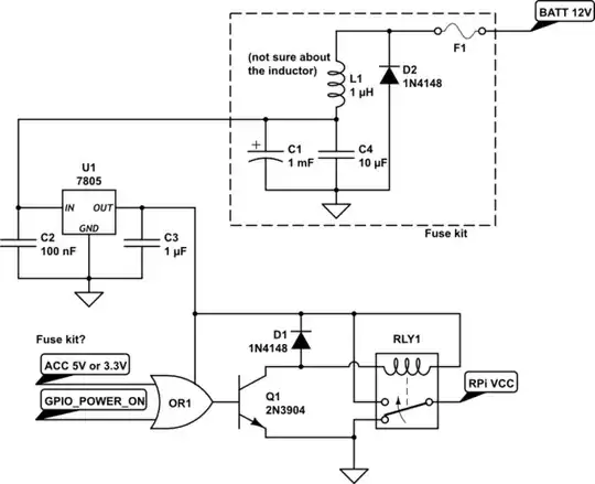
Software running in the RPi will set one of the GPIO pins high, presumably when the RPi shuts down the GPIO pins will all go low. So Q1 should turn the relay on, keeping the RPi's power on as long as the ignition is on, or the GPIO pin is high.

I have 3 fuse kits with a 1000uF cap and some kind of transformer/inductor, so I may as well use one of them on each the 12V battery and 12V accessory line.

This shut down controller claims to draw only 50uA in standby - if I used a CMOS 4071 OR gate that would be a start, but from what I've read, you'd need more current from the OR gate to saturate the transistor - is that right?

Bearing in mind that I need to level-shift 5 lines from 3.3V to 5V and 2 from 5V to 3.3V in addition to the requirements of this sub-circuit, can anyone recommend components/alternatives for OR1, Q1, RLY1 and/or any modifications?

schematic

simulate this circuit – Schematic created using CircuitLab

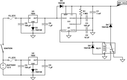
Here's my attempt at following @Connor Wolf's suggestion.

  • R1 and C3 need to be be chosen to allow the RPi to shut down properly
  • I've added C1 because I image that it will take a brief moment before the relay switches after the ignition is turned off - I've got no idea how long that is, but I suppose the RPi is going to be drawing about 700mA from the capacitor, in addition to the 555 and relay

schematic

simulate this circuit

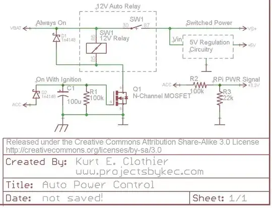
@Nick suggests it could be simpler - like this perhaps? I tried to remove the diodes so that I could just use an off-the-shelf 12V-5V 1A USB power supply (or a pair of them). The 555 datasheet says that it outputs 3.3V (max source 100mA? This page says 200mA). The RPi will take read the ACC line at 3.3V to determine when to shut down.

schematic

simulate this circuit

Nicholas Albion
  • 285
  • 2
  • 3
  • 10
  • 1
    Your 7805 is going to get **REALLY HOT** as your circuit is drawn. With the 700 mA draw of the raspberry pi, at your vDrop of 7V (12v-5v), you're going to be dissipating **4.9 watts** (7V * 0.7A) in the regulator. You *really* need to look into a DC-DC for that. – Connor Wolf Mar 22 '13 at 08:06
  • 1
    Also, your "fuse kit" thing is drawn incorrectly. Right now, the diode is simply shorting out the 12V input, and the inductor isn't doing anything. I would guess that the inductor is in series with the power line, and the diode is the other way around (which would let it prevent reverse-biasing the input). – Connor Wolf Mar 22 '13 at 08:08
  • 2
    Voltage dividers are not a good way of powering anything, as the load varies the voltage will vary. Just use a regulator of some sort, they're cheap & plentiful enough. – John U Mar 22 '13 at 08:40
  • @ConnorWolf I've got a 7805CT which is rated at 1A. ...Does that only apply if you're coming down from 6V to 5V? When I Google for DC-DC converter many of the search results mention 7805. Unless the DC-DC converter outputs 5.7V I think I'd need to switch D2 and D3 for schottky diodes with a voltage drop of less than 0.25V – Nicholas Albion Mar 23 '13 at 03:20
  • @NicholasAlbion - I didn't say it wouldn't work, just that you're going to need a very large heatsink, or a fan/smaller heatsink, to keep it properly cool. – Connor Wolf Mar 23 '13 at 03:31
  • Watch out for the high voltage spikes on the battery in cars. You can use a TVS diode or a varistor to protect the input of 7805. – abdullah kahraman Mar 23 '13 at 12:48
  • You may want to consider a decent car USB charging adapter as a basis for your power supply; a *decent* one always contains a switched converter wich minimizes heat dissipation. For lower currents (<= 100mA) I have used circuits like [this one](http://www.mikrocontroller.net/attachment/124404/7-Schutzschaltung.jpg) [(source/parts)](http://www.mikrocontroller.net/topic/236341#2395310) for years in automotive environments. – JimmyB Mar 23 '13 at 19:24
  • @ConnorWolf can you elaborate on the "REALLY HOT" -> DC-DC? I installed my circuit board with RPi in the car, ran for 5 minutes, and even with a 2x4cm heatsink it managed to burn my fingers. A 1Amp 7805 is definately not fit for this purpose. – Nicholas Albion Apr 10 '13 at 13:47
  • Could you not just have a relay that switches when the car ignition is switch on? Get the Pi to detect its been switched off and then shutdown the Pi gracefully... –  Mar 24 '13 at 23:50
  • The relay would switch off the moment the ignition is switched off. ..Then what? I need to buy the Pi 10 seconds or so after the ignition is turned off, then cut all power. – Nicholas Albion Mar 25 '13 at 11:56
  • A 5V ~5F super cap would provide ~6.25W for 10 seconds and cost ~$10-15. Just be careful not to short it and control the charging current in a reasonable way. – Mark Mar 26 '13 at 18:06
  • According to [this answer](http://electronics.stackexchange.com/questions/60622/circuit-to-safely-power-down-raspberry-pi#60626) I'd need about 30F, so multiply your $10-15 by 5. – Nicholas Albion Mar 27 '13 at 11:08
  • Note that the 'Pi is specified @ 700mA **max**. You may want to measure the actual current drawn in your application. It may be well below those 0.7A if the device is not running at full load (CPU + GPU @ 100%, massive network load, etc.). If it draws only an average of 100mA, for instance, a given capacitor will last much longer. – JimmyB Mar 27 '13 at 15:25
  • It is wrong to use a capacitor for this purpose – drzymala Mar 28 '13 at 22:40
  • @martini - no, it's actually quite normal to use a capacitor to give time for safe shutdown - the problem is more that the pi, not having been designed for such use, is a bit of a power hog. – Chris Stratton Sep 25 '13 at 20:37
  • Use a HAT like this one to provide uninterrupted power from a battery and then detect Car ON or Car OFF. Startup or shutdown as appropriate. https://www.pi-supply.com/product/ups-pico-uninterruptible-power-supply-hat/ –  Sep 27 '15 at 13:06

4 Answers4

9

While using a one-shot timer circuit will work, I think an easier solution can be used. Take a look at this circuit.

enter image description here

For clarification, "VBAT" is a 12V source that is always on as long as the battery is connected. However, "ACC" is a 12V source that is only on when the ignition is on or the key is set to "accessory." Rather than using a 5V relay just to control the power to the RPi, why not use a standard 12V auto relay as shown. This way, there is no wasted power (except for the coil current while the power is on) because everything will be disconnected from the battery.

One side of the coil is always connected to 12V. The opposite side is connected to ground (chassis) through an N-Channel FET (Q1). While a MOSFET is used in the diagram, any FET capable of sinking the coil current can be used. When "ACC" is powered ON, Q1 will switch ON, connecting the coil to ground and actuating the switch. This will in turn power whatever 5V regulation circuit you plan to use (a simple 7805 regulator with heat sink, a switching DC-DC converter, the USB supplies mentioned, etc).

The diode D2 is there to ensure the capacitor can only discharge into Q1 and can be regular or Shottky. Other methods should probably be used for over voltage and current protection from the battery.

The "ACC" voltage can be put through a voltage divider to create a 3.3V signal for the RPi. Be careful with this voltage level, considering a 12V auto battery can really be more like 14V DC. As long as this signal is HI, the RPi knows that the power is on. Obviously, this GPIO pin should be set as an input with any internal pullups disabled. When "ACC" is turned off, the RPi should see the LO signal on the pin and begin its shutdown.

When the "ACC" voltage is turned off, the capacitor C1 will retain the charge for so long, discharging through the resistor R1. Once the capacitor voltage drops below the gate threshold of Q1, it will switch OFF, disconnecting the relay coil from ground and removing power from the peripheral circuit. If a "logic level MOSFET" is used for Q1, it will remain switched ON until C1 voltage is fairly low. I tested this circuit using an NTD4960 (Datasheet), and it remained on for around 15 seconds - until C1 was around 2V. To increase the time, increase the capacitance value.

PeterJ
  • 17,131
  • 37
  • 56
  • 91
Kurt E. Clothier
  • 4,419
  • 18
  • 31
  • How do I select an appropriate FET? I have a 12V relay already - 621D012 (270ohm -> 44mA) The online [Jaycar catalogue](http://search.jaycar.com.au/search?p=Q&lbc=jaycar&uid=173601829&ts=custom&w=mosfet&method=and&view=list&isort=price) lists the following: 2N7000, PN100, VN10KM, IRF540N, IRF1405 and more – Nicholas Albion Mar 27 '13 at 12:06
  • 1
    I believe the 2N7000 would be a good choice, but here is what you are looking for... Type: N Channel FET (not an NPN BJT); Forward Current (I_d): At least 100mA - (double of 44mA); Gate Threshold Voltage (V_gs or V_gth): No more than 3V; Gate Capacitance: Doesn't matter, we put more externally! "ON" resistance (R_ds): low is good, but your power dissipation will be low; Power Dissipation (P_d): 44mA ^2 * R_ds << at least double this – Kurt E. Clothier Mar 27 '13 at 19:38
  • Can this be store bought? I am trying to do the same as the OP but I have not idea on how to create my own circuits. Are there any store bought solutions for this? – John Demetriou Nov 03 '14 at 11:50
2

Honestly, I think you're overthinking this a lot.

Personally, I'd just use a one-shot with a period of a minute or two, triggered by the car being turned off.

When you turn off the car, the one-shot fires, holding the relay closed until it times out. All you would need to do would be ensure that your raspberry pi shuts down within a minute or two of the car being turned off. This should be easy enough by monitoring a input from the car's switched power.

The biggest advantage to a system like this is that when your software crashes (when, not if), it'll still shut down anyways, so you won't wind up with a dead battery. The one-shot should be plenty simple. You could use a 555, or a little microprocessor (like Olin will suggest).
Another nice thing is that, if you do the design properly, the system can disconnect itself from the car battery, ensuring the quiescent current draw is absolutely 0.

Connor Wolf
  • 31,938
  • 6
  • 77
  • 137
  • sounds great - how is it done? – Nicholas Albion Mar 22 '13 at 13:05
  • Sounds a bit like the circuit used to keep cortesy lights on, after the car door closes. From memory, a capacitor is charged to 12V and holds on a FET or similar. Remove power, the cap slowly discharges - until the FET gets switched off. – Alan Campbell Mar 26 '13 at 07:05
  • The RPi draws 5V at about 700mA and I think I need about 10 seconds to shutdown. Using a capacitor was my first thought, but that would involve about $100 worth of capacitors – Nicholas Albion Mar 26 '13 at 13:09
  • @NicholasAlbion, the cap wouldn't be used to provide power directly to the Pi, but a gate voltage to a FET (which would be controlling a relay). The gate resistance of a FET is very high, so you wouldn't need a big cap to last the 10 seconds needed. – Pentium100 Apr 01 '13 at 03:38
0

Any fixed delay method suffers from the problem of not knowing how much time the RPi really needs to shut down. It would be better to press a button that signals the Pi to shut down, it could then do what it needs for a clean orderly shutdown, taking as long as needed, then issue a GPIO signal back to the push button circuit that shuts down the power. That gives the RPi as much time as it needs to do things like safely shut down the SD card. The circuit doesn't have to be too complicated. You can see a simple circuit at

http://www.mosaic-industries.com/embedded-systems/microcontroller-projects/raspberry-pi/on-off-power-controller

The web site describes the circuit's operation.

  • You make a good point, although I don't think anyone wants to have to go through such a process every time they shut off their car. It would make more sense for the RPi to sense the shutdown by monitoring the voltage of the ACC line (only on when the car is on), then kill its own power from the "always on" 12V line when it is ready to do so - automating the system. – Kurt E. Clothier Apr 22 '13 at 21:14
-2

Use 4 AA rechargeable batteries. Power the Pi from them and have them on charge from the car's battery.

Use 1 GPIO to tell the Pi if the ignition is on or off.

Shutdown when ready.

  • 4
    I think this answer needs more detail to be useful. Maybe post a schematic or desciption on how you think this would work and what sort of charging circuit / device/ power control you would propose. – PeterJ Sep 25 '13 at 12:26