3

I would like to design a system that produces -10 degrees and +10 degrees phase shifts at 409.6MHz (Basically BPSK).

The way I'm thinking about approaching this is by using a DDS to generate the BPSK at 12.8MHz and up-converting using a mixer to 409.6MHz, filtering, and amplifying to +10dBm.

Is this the best way to do this? I have also read that I can use a 32x PLL multiplier... would that be a better way?

Factors I am taking into consideration:

  1. Complexity to design circuit/pcb

  2. Cost of components

  3. Low phase noise, low spurs, emi, etc.

  4. Using a 12.8MHz ovenized oscillator (as 12.8 x 32 = 409.6)

hassan789
  • 2,106
  • 4
  • 21
  • 34
  • What data rate are you wanting to run at? – Andy aka Mar 27 '13 at 17:38
  • 500 bits per second – hassan789 Mar 27 '13 at 20:53
  • According to Wikipedia, [BPSK](http://en.wikipedia.org/wiki/BPSK) has two points at +90 and -90 (or equivalently +0 and +180) degrees. I am curious -- why would anyone want to use "-10 degrees and +10 degrees"? (Should this be a separate question?) – davidcary Jun 26 '13 at 04:45
  • @davidcary To reduce the signal bandwidth. – hassan789 Jun 26 '13 at 12:02
  • My understanding is that transmitting at -10 and +10 degrees is mathematically identical to transmitting an unchanging pilot carrier at 0 degrees and simultaneously transmitting a normal BPSK signal at -90 and +90 degrees, where the amplitude of the BPSK signal is smaller than -- tan(10 degrees) of -- the amplitude of the pilot. [Phil Karn](http://www.ka9q.net/vmsk/) seems to say that doesn't reduce the *real* signal bandwidth -- the frequency spacing required to avoid interference -- although it may appear to have a narrower bandwidth on a spectrum analyzer. http://en.wikipedia.org/wiki/VMSK – davidcary Jun 27 '13 at 14:15
  • Good point. I think you are correct! For my application, I am using Narrow Band SBPSK (shaped bpsk). Does your analysis hold true when you shape the symbol phase? – hassan789 Jun 27 '13 at 21:27
  • Yes, if you have any kind of RF communication whatsoever, then you then add some fixed unchanging pilot carrier, it doesn't change the real signal bandwidth required -- even when the result appears to have a narrower bandwidth on a spectrum analyzer. – davidcary Jul 01 '13 at 16:06
  • Shaped symbols require less bandwidth than square pulses. Like all known communication techniques, shaped symbols require more than the minimum bandwidth given by the [Shannon-Hartley Theorem](http://en.wikipedia.org/wiki/Shannon-Hartley_Theorem). Some types of shaped symbols have another advantage: [more energy-efficient amps](http://en.wikipedia.org/wiki/Linear_amplifier) than the linear amps required for QAM. Shaped symbols are used in [minimum-shift keying](http://en.wikipedia.org/wiki/minimum-shift_keying) and [shaped-offset QPSK](http://en.wikipedia.org/wiki/Phase-shift_keying#SOQPSK). – davidcary Jul 01 '13 at 16:53

2 Answers2

2

The best way to go about doing this is basically bypassing the DDS altogether and generating the baseband from a DSP and generating the symbols using a IQ Modulator. A VCO based PLL can be used to generate an LO for the modulator.

Additionally, the magnitude of the I & Q baseband voltages has the following relation:

Vq = -tan(10°) * Vi
Vq = -tan(-10°) * Vi

enter image description here

hassan789
  • 2,106
  • 4
  • 21
  • 34
2

A design worth considering is a colpitts oscillator with an ADF4111 PLL controlling centre frequency via a varactor diode (other PLLs I'm sure would work just fine). Here's a simple picture of one and I'd replace the transistor with a BFR92A transistor. R4 should be shorted out for decent ops at 400MHz. It's an FM modulator and works nicely. The FM can turn to PM by differentiating the data.

enter image description here

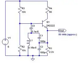
The varactor would be in series with about 22pF from the top of the inductor. The other end of the varactor would be ground and the dc control thru a 10k from the PLL. This pretty much describes a circuit I once designed. I added an extra transistor fed from the base - this was an emitter follower output to a filter and simple antenna. It only produced 0dBm from a 3.3V supply so you may need to run it from a bigger supply or add an amplifier.

You can feed the data (after differentiating and amplitude reduction) via a small capacitor to the varactor. The downside of this is that it needs a little care seting up and if you are not hyper-bothered about the exact phase shift then it should be ok.

A further note about the ADF4111 - it needs a small MCU to set up its registers and a xtal for a frequency reference.

Andy aka
  • 434,556
  • 28
  • 351
  • 777
  • this is an amazing circuit. How can I design other circuits like this? Is there a specific book you can recommend? – hassan789 Mar 28 '13 at 01:18
  • @hassan789 No specific book to recommend I'm afraid to say - but maybe someone else can recommend one. Maybe you should start another question on this basis. I'm sure there'll be some good answers – Andy aka Mar 28 '13 at 10:22