1

I have been working with the AD8232 ECG modules for a while now and I am trying to figure out what the raw ECG outputs from this module correlate to. I cannot seem to find any information from their datasheets as to what these output values represent and how I can go about converting them into millivolts (mV). It currently outputs analog values but essentially I want to know if there is a calculation to reverse these outputs back to the raw ECG that would have passed into the device.

Any assistance or guidance in converting these values to mV would be greatly appreciated.

For reference, here is a link to the datasheet: https://www.analog.com/media/en/technical-documentation/data-sheets/ad8232.pdf
  • 1
    There's a lot of gain stages in that part which makes it confusing. A [SPICE macromodel](https://www.analog.com/en/products/ad8232.html#product-tools) exists for the part. Perhaps you can get a better understanding of the part through simulation. – qrk May 02 '22 at 00:27

1 Answers1

2

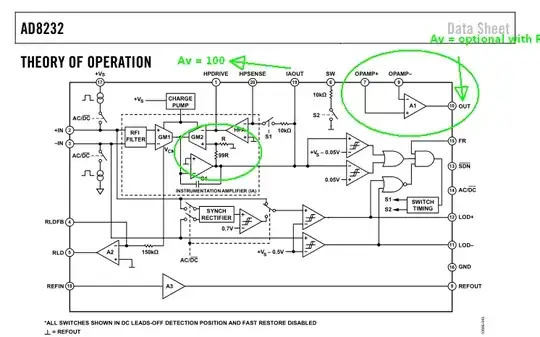
Although there are filters involved with HPF and LPF, the main signal gain is Av=100 for IAOUT and optional Op Amp for further gain for OUT.

enter image description here

https://www.analog.com/media/en/technical-documentation/data-sheets/ad8232.pdf

Tony Stewart EE75
  • 1
  • 3
  • 54
  • 182
  • Hello, thank you for your reply. I would be quite a novice in this field so could I ask for an expansion on your answer. How can I manipulate the main signal gain in calculating the ECG mV equivalent? – Dev_Engineering_ May 03 '22 at 15:07
  • The 1st stage attenuates feedback by R/(99R+R) so the forward gain is this feedback ratio. Thus Av=100 is fixed except for the filter impedance ratios externally. So take IAOUT and divide by 100. The OUT signal also depends on TBD negative feedback impedance ratio from OUT to A1- input to determine its gain – Tony Stewart EE75 May 03 '22 at 15:19
  • Thank you again for your response, Tony. I slightly follow this and I just wanted to play my understanding of what I want to achieve to see both if it actually makes sense and if it correlates at all with your answer. Essentially, I have seen in medical ECG settings that the that the outputs from these range roughly from +/- 3mV. If this chip operates at 3.3V, how I understand it as an example, if an output representing 2.3V it would translate to something like 0.8mV and so on. I am unsure if this is the correct way of approaching it but I welcome clarification. Many Thanks. – Dev_Engineering_ May 04 '22 at 16:27
  • 1
    It does not depend on 3.3V for gain. Only the actual resistor ratios in your circuit card around the Op-Amp times the 100 1st stage. Here is one example https://download.mikroe.com/documents/add-on-boards/click/ecg-5/ecg-5-click-schematic-v101.pdf Input is divided by 2 with 1M's to OPin+ then the filter feedback has a DC gain of 1+1M/100k then = 11/2 so 5.5 is the 2nd stage gain and total is 550. Then e.g. if output is 1.1Vpk then input is 1.1/550 = 2.0 mV. Compare yours to this. – Tony Stewart EE75 May 05 '22 at 00:13