0

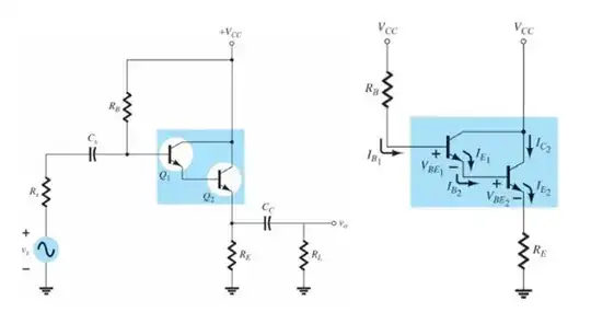
As you may see from title, I made a darlington transistor like this.

enter image description here

I set each transistor(Q1 and Q2) to have β = 150. So, total darlington β must have 22500 or thereabouts according to a formula below.

enter image description here

But, total β from my LTspice comes out to 16485.5871

And according to my calculation,

enter image description here

enter image description here

enter image description here

VE has to be equal to 1.6489V(theoretical value).

But, VE in my LTspice circuit comes out like this.

enter image description here

That's really odd... I thought I designed my circuit in LTspice correctly so it could be same as theoretical values. But it turns out to be different.

Maybe, did I calculate theoretical values? Or Did I make a mistake when I design a darlington transistor in LTspice?

Please help me, friends...

If you need more information, please request. I'd be more than happy to give you!

enter image description here

user299980
  • 73
  • 5
  • 2
    Try adding an IKF=10 to your models. That should nail it. Your problem will be in the final BJT (mylittleNPN1.) So you could just set it there, instead, I suppose. If you want to know partly why that thing exists, look [here](https://electronics.stackexchange.com/a/305720/38098) and consider region III. – jonk Apr 30 '22 at 03:10
  • Thank you for answering my question. But I put an IKF=10 to two models. But, it still doesn't work correctly. – user299980 Apr 30 '22 at 03:40
  • 1
    What does "doesn't work correctly" mean, in numbers? – jonk Apr 30 '22 at 04:28
  • 2
    Just checked on my side of the universe. [Looks pretty good over here](https://i.stack.imgur.com/RTHuN.png) to me. – jonk Apr 30 '22 at 04:35
  • Thank you for making my circuit yourself in your LTspice for me. Actually, I don't have a problem about respective BJTs' β. When I measure a beta of Q1 and Q2, they individually come out to 150 or thereabouts. My problem is that a VE is 8V in my LTspice but in my theoretical calculation a VE turn out to 1.6489V. And "doesn't work correctly." was used to mean that the VE came out around 8V instead of 1.6489V even though the modification was made as you said(Try adding an IKF=10 to your models). – user299980 Apr 30 '22 at 05:10
  • 2
    But \$V_E\$ is \$V_E = I_ER_E = 8.3511V\$ and \$V_{CE}\$ is \$V_{CC}- V_E = 1.648V\$ – G36 Apr 30 '22 at 05:13
  • 2
    @user299980 Why would that be an issue? You have:$$10\:\text{V}-50\:\text{K}\Omega\cdot I_{_\text{B}}-V_{_{\text{BE}_2}}-V_{_{\text{BE}_1}}-51\:\Omega\cdot I_{_\text{B}}\cdot\left(\beta_1+1\right)\cdot\left(\beta_2+1\right)=0\:\text{V}$$Solve that for \$I_{_\text{B}}\$. I'd estimate \$V_{_{\text{BE}_2}}=650\:\text{mV}\$ and \$V_{_{\text{BE}_1}}=800\:\text{mV}\$ and find \$I_{_\text{B}}\approx 7.05\:\mu\text{A}\$. From that I'd get the emitter voltage of \$Q_1\$ as \$\approx 8.2\:\text{V}\$. Nothing strange I see. – jonk Apr 30 '22 at 05:16
  • 1
    Oh my......... I'm terribly sorry for you guys........ I made a mistake when I calculate a VCE2. If you see my calculation, You can find I wrote VCE2 is equal to VE........ I wish the ground would swallow me up. I'm really really sorry, guys..... – user299980 Apr 30 '22 at 05:36
  • And thank you so much for letting me realize my mistake! – user299980 Apr 30 '22 at 05:41
  • 2
    @user299980 It's no problem. We've all been there... many times. ;) – jonk Apr 30 '22 at 06:09
  • 3
    @user299980 I'm glad the problem has been solved, but you need to provide a source for the pictures if they were taken from 3rd party sites, to avoid plagiarism (something to do with the site's rules, or something). – a concerned citizen Apr 30 '22 at 06:26

0 Answers0