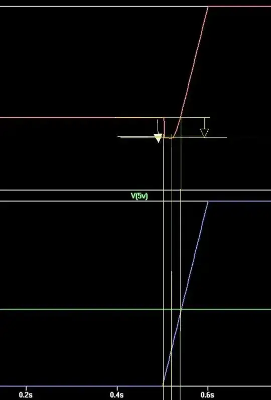
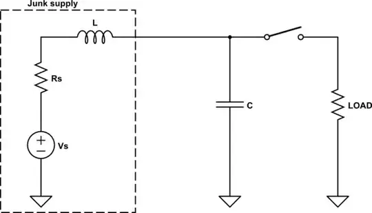
1

In the circuit below, I get a quiescent current (entering positive supply and leaving negative supply of the op amp) of about 497 µA, while the load current is only 5 µA. I am aware that this purported quiescent current has no real-world significance, but my issue is that it is a nuisance when simulating low-power circuits.

It was the same for all levels of the UniversalOpamp in this circuit, with the exception of levels 1 and 4, which displayed no supply current at all (not modeled).

In other circuits, the quiescent current turned out to have different values.

Does this follow any logic ? I had guessed that the UniversalOpamp2 would have no quiescent current, but it seems like it takes a random amount which I cannot really control. So is there a way to either prevent the quiescent current or - even better - set it to a specific value ?
enter image description here

Null
  • 7,448
  • 17
  • 36
  • 48
tobalt
  • 18,646
  • 16
  • 73
  • I must admit I'm not familiar with the SPICE models behind UniversalOpamp and [UniversalOpamp2](https://github.com/evenator/LTSpice-Libraries/blob/master/sub/UniversalOpamps2.sub#L15), but seeing their names, they are just some rough idealized abstraction for real-world opamps, and I think it's a bit of a stretch to assume their quiescent current has any real-world significance. – Marcus Müller Apr 22 '22 at 07:28
  • @MarcusMüller exactly. That is why I would have assumed that it wouldn't even have any quiescent current! The fact that they have, is a pure nuisance when simulating low power stuff. Because, of course, this has no real world significance and I want to get rid of it. Ill edit to make it more clear. – tobalt Apr 22 '22 at 07:36
  • 2
    but if it's a nuissance, then just give it its own independent voltage source? – Marcus Müller Apr 22 '22 at 07:50
  • @MarcusMüller This would be quite a complication, because in low-power designs also my power sources have high output impedance and I must know/simulate to which extent they are loaded down during operation. Unfortunately, LTspice doesn't have a current controlled current source. I could use the latter in combination with a UniversalOpamp1 to simulate supply loading. – tobalt Apr 22 '22 at 07:56
  • ok, but now you're just saying "I need a model that accurately models a real-world Opamp power consumption; yet, I use a model that is decidedly *not* a model of a real-world opamp": I don't know how that helps overall? If accurate modelling of the current draw is important, then you can't just use an opamp model whose declare purpose is to be simplified enough to not include such detail. – Marcus Müller Apr 22 '22 at 07:58
  • 2
    @tobalt LTspice does have a CCCS, it's a primitive that has existed since 50 years ago SPICE: the `F` source. Teh controlling source needs to be one of: a voltage source (the "classical" way), a VCVS, or an inductor. I'm writing an answer now to address your issue. – a concerned citizen Apr 22 '22 at 07:59
  • @MarcusMüller In an ideal world, you would be right. But some manufacturer models are so bad that they are worse than the UniversalOpamp not only in terms of OP convergence but also they give rise to strange *unreal* behavior, like active supply current *generation* when no supply is connected or is shutdown. – tobalt Apr 22 '22 at 08:02
  • in that case, watch out for a concerned citizen's answer: it will (probably) show you how to (low-hassle) make a voltage source that is isolated (but depends on the voltage source for the rest of the circuit), and you can then just, to the rest of the circuit, add a model of only the current consumption of some somewhat-realistic opamp model – Marcus Müller Apr 22 '22 at 08:06
  • @tobalt `UniversalOpamp1` is a barebones OTA (the equivalent of a G + R||C), and 4 is a behavioural approach, that's why you saw those results. – a concerned citizen Apr 22 '22 at 08:17

2 Answers2

4

[Opamps]/UniversalOpamp[2,3a,3b] use VCSW as the output stage, and the quiescent current is directly related to the values of Ron/Roff, since the switch has a resistance that depends on the logarithm of the conduction. The solution is to change these values so that they match your preferences. For example, here's how it looks like when varying Ron, for this equivalent circuit (as far as the output stage is concerned):

Ron influences the current

Stepping Roff while keeping Ron=1 will show the exact same currents. So, if your application is for very low power, you can assume both a higher Ron and Roff, so you could make them Ron=100 Roff=1T, which will give you a 1.2 μA. The ratio will be less than the recommended maximum of 1e12, to avoid numerical issues.


To modify Ron/Roff open up the Documents/LTspiceXVII/lib/sub/UniversalOpAmp[2,3a,3b].sub and look for this line:

.model Q SW( ... )
a concerned citizen
  • 21,167
  • 1
  • 20
  • 40
  • 1
    Thanks! I managed to create a new part which I called UniversalOpamp2LP which makes use of your recommended modifications. It works very well. – tobalt Apr 22 '22 at 10:17
  • @tobalt Happy customers, best customers. – a concerned citizen Apr 22 '22 at 13:47
  • Off-topic but tangentially related...do you know there's a known equivalent circuit for the A-device OTA or if anyone has reverse-engineered it? Asking for a friend. – Ste Kulov Apr 23 '22 at 11:33
  • 1
    @SteKulov I don't know, but I suspect Mike just took the `opamp.sub` to the next level with `tanh()` & co, that can be done much better under the hood. If you look in `[SpecialFunctions]` there's also an `odev` (and `odev2`), which I think is related to the `OTA` (there is a post in the LTspice groups about it, somewhere), and maybe even to the "hidden" parameters `dir/Vto` for the VCCS. – a concerned citizen Apr 23 '22 at 13:40
0

Found this about "MacroModels".
Don't know if this applies to UniversalModelx (models not known).

Here is what I get with microcap v12, case levels 1(ideal), 2(3 stages), or 3(Boyle). EE&O.

For reference :

enter image description here

As one can see, zero quiescent currents at levels 0 and 1.
The current supply is to be compared with the current load (R1+R2).
NB: R3 current (internal ?) not taken into account in supply?

enter image description here

enter image description here

enter image description here

Antonio51
  • 11,004
  • 1
  • 7
  • 20
  • It looks like the levels mean something quite different in microcap than in LTspice. Thanks for checking. – tobalt Apr 22 '22 at 08:29
  • No worries ... I did not add level 3 for opamp (differents when BJT used are NPN or PNP, or FET-N or FET-P ...) – Antonio51 Apr 22 '22 at 08:32