A circuit to soft-start, a.k.a. slew-limit, the charging of a 220 uF capacitor Cf at a maximum current in the neighbourhood of 300 mA. Cf is a filter cap preceding a further SMPS stage. My plan so far is to use an ESL227M035AG8AA, an aluminum electrolytic chosen for its ESR of 48 mohm @ 100 kHz. 220 uF was slightly arbitrary, only chosen because the SMPS asks for a minimum of 20 uF at the input with low ESR, and the 220 uF cap is the cheapest in that category.
Tony says that
If ESR * C <= 10 us ( for low ESR type e-caps) then Ic max = Vin/ESR = Vin * C /10us = 18V * 22 = ~ 400 Amps
In this case this would be basically true, because 48 mohm * 220 uF = 10.56 us; and 18 V * 220 uF / 10.56 us = 375 A.
Vin between 12 and 18 V. This is automotive line voltage but can go that high due to some non-standard modifications from hobbyists for this application.
Maximum continuous load is 1.1 A. The load is a simple SMPS powering a LED driver. The SMPS has its own soft-start circuit but of course can only protect its output, not capacitors at its input.
U1 would be replaced based on design parameters but a quick hack uses the default PMOS model for simulation.
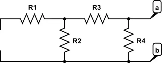
simulate this circuit – Schematic created using CircuitLab

Based on a related question, at these time scales U1 risks entering thermal runaway and there is barely any other resistance in the charging path so it could fry due to the Spirito effect. However, am I right in thinking that if I use something like the MCG35P04 which has only a weak thermal effect against Vgs:

then runaway may be mitigated?
It's possible to replace the PMOS with an NMOS and put it only in the charging path of the capacitor:
Speaking more broadly, it surprises me that manufacturers don't seem to offer integrated soft-start circuits for this purpose - only soft-start sections in other components like SMPS or load switches. Why is this?