1

I'm trying to build an automatic night light circuit based on some designs I found online.

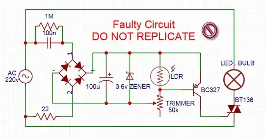
Here's the circuit I built:

circuit diagram

The problem is that the transistor BC327 keeps failing. The circuit works for a couple of seconds and suddenly the transistor doesn't turn off anymore, sometimes it happens while it's running and sometimes it happens when I unplug and re-plug the power couple of times.

The capacitive dropper circuit is supposed to limit the current to about 7 mA (measured it with a multimeter,) but I tried to place a 100 ohm resistor on the transistor base and also the TRIAC gate. I also tried using an NPN transistor instead (2A2222), but still the same problem.

A couple of times the 22 ohm inrush current resistor (1/4 W) got burned when I plugged in the power.

I'm really struggling with this circuit and burned a dozen of transistors in couple of days. I really want to know what is the problem rather than just fixing the problem by using another design, so I'd really appreciate it if you could help me figure out what's wrong with my circuit.

Please tell me if you need any additional information.
JRE
  • 67,678
  • 8
  • 104
  • 179
  • 1
    the 22r needs to be much bigger, and the 100u needs to be smaller; you don't need such a big cap when you regulate. – dandavis Apr 21 '22 at 07:24
  • Reducing e-Cap is *possible* but not necessary by same ratio with 22R going to 1k but the cap C value was not the main cause of failure FWIW @dandavis. – Tony Stewart EE75 Apr 21 '22 at 11:18
  • I actually originally was using a 10u capacitor but thought it was not enough to handle voltage spikes so I replaced it with 100u. – Mohamed Gharib Apr 21 '22 at 12:52
  • Most designs I found was not even using inrush current resistor, I added the 22 ohm based on some calculations and suggestions (higher value needs higher wattage resistor), and replaced it with 1k and still. – Mohamed Gharib Apr 21 '22 at 12:56
  • Parasitic C in Triac may be inducing spikes so adding RF cap to gate may suppress that, but adding DIAC changes everything is best scaling opto switch up x10 in voltage, lower current then discharge cap is reduced to drive Triac. But then you get identical drive in both quadrants. – Tony Stewart EE75 Apr 21 '22 at 14:49
  • Check you have the triac connected correctly. Main Terminal 2 should be connected to the bulb. Main Terminal 1 to the ac supply. –  Apr 21 '22 at 18:10
  • 1
    ..... and also ensure that the bulb is connected to the same side of the ac supply that the 100n cap is connected to and that MT1 is connected to the same side of the ac supply that the surge protection resistor is connected to. (22R in the diagram). –  Apr 21 '22 at 18:55
  • You need to take great care with that type of circuit. If you were to connect the Neutral to the 100n cap and the Live to the 22R protection resistor then the whole circuit would be swinging between about +310V and -310V. This type of circuit is dangerous! –  Apr 21 '22 at 19:08
  • @TonyStewartEE75 will remove the triac from the circuit and add an LED to try check which component is causing the failure. – Mohamed Gharib Apr 21 '22 at 19:10
  • @James it is exactly as drawn, one time I messed up & swapped the ac lines going to the cap and the bulb, the 22R kept burning instantly when plugged in, until I figured it out. – Mohamed Gharib Apr 21 '22 at 19:13

2 Answers2

5

After asking in other places, I found the problem, or rather problems:

There are a couple of problems causing the transistor to fail here, the first one is a huge current spike through the capacitor on power up through an almost direct short path when the capacitor is first charged as shown below:

enter image description here

There's another problem caused by current being fed back to the transistor collector->base from the TRIAC, also probably voltage spikes.

That's not all, but in summary it's just wrong to drive the TRIAC with a transistor, it needs a proper TRIAC driver.

1

If you consider the Pot at one extreme as only 5% of the total value and the caps as 0 ohms during the peak voltage, a casual estimate of the current should explain the power dissipation problem with P=V^2/R.

Change 22 Ohms to 1k 1/4W and expect temperature to rise 50'C, smaller will be cooler but will still avoid the inrush.

Add around 1k to 2k between pot and PNP base to limit both base and collector current.

You might still need a DIAC to trigger the TRIAC to avoid unequal trigger current levels near twilight threshold and burn out the light bulb AC to DC converter possibly on half wave rectification try to boost the voltage if not rated for half wave voltage.

Parasitic gate capacitance might also be breaking down the PNP so an RF cap might be a bandaid

Tony Stewart EE75
  • 1
  • 3
  • 54
  • 182
  • Replaced the 22 ohm resistor with a 1k, added 2.2k on transistor base, plugged the power and the pulp is always on, measured the transistor and it's now blown (100 ohm between collector and emitter), I think it's a voltage spike problem but I can't measure it with the multimeter. – Mohamed Gharib Apr 21 '22 at 12:47
  • about the diac, the triac is been triggered with 3.6v so a 30v diac is not going to work, right? – Mohamed Gharib Apr 21 '22 at 12:49
  • Changes to scale up x10 are needed and add small C dumped by DIAC into gate – Tony Stewart EE75 Apr 21 '22 at 16:40
  • then there is always this https://www.edn.com/automatic-night-light-feeds-directly-from-the-ac-line/ This doesn't use the problematic PNP – Tony Stewart EE75 Apr 21 '22 at 16:54
  • the transistor needs low voltage so cannot scale up x10 to use a diac. – Mohamed Gharib Apr 21 '22 at 19:16
  • this is a promising circuit I shall try it out, but I need to figure out what's wrong with my circuit for learning reasons because on paper it's supposed to work and it's messing up my understanding so it's important to me to solve it or at least know the problem – Mohamed Gharib Apr 21 '22 at 19:20
  • also because I need this kind of small capacitive power supply for future projects so I need to have confidence it can work properly. – Mohamed Gharib Apr 21 '22 at 19:24
  • 1
    You can simulate on Falstad's if you know the junction capacitance to add. Then choose 90 deg for Vin and reset. You can display anything and everything V,I,Pwr, Pwr avg – Tony Stewart EE75 Apr 21 '22 at 23:24
  • I'm actually using it, falstad is such an easy & useful tool I use all the time, anyway I removed the triac, the transistor is not failing anymore, I did more studying for the triac and I might've figured it out, the transistor in the current configuration allows negative current to flow back from the triac in the negative AC wave which might be causing the transistor to fail (not sure), placing a diode or using NPN on the high side could fix it but will trigger the triac only on half of the wave signal, anyway I'll test it out to confirm the theory and try to figure out a solution after that. – Mohamed Gharib Apr 22 '22 at 00:50
  • Maybe reconsider what works best and low cost https://www.monolithicpower.com/en/mp158.html – Tony Stewart EE75 Apr 22 '22 at 04:28