The OP question is seemingly naive but as can be seen from the many posts, it concerns important circuit concepts. It can be answered with banal clichés such as "op-amp follower" or "transimpedance amplifier" as can be seen in millions of web pages. But it is much more meaningful and useful for the OP and all of us to reveal the basic ideas behind these specific circuit solutions. Then let's do it...
The happy circumstance
It is a happy coincidence for me that, over the past two weeks, I have decided to conduct with my students, in the subjects in Electrical Engineering (1st year) and Basic Electronic Circuits (3rd year), two unusual laboratory exercises dedicated to this topic. I figuratively called them "Ideal" voltmeter and "Ideal" ammeter. While for junior students the goal was the electrical ideas and circuits themselves, for seniors the goal was more the applications of these ideas in the ubiquitous non-inverting and inverting op-amp circuits with negative feedback.
The problem
As in the OP question, so in most answers here, the current through the closed switch and the voltage across the open switch are determined by calculation or common sense. But these are only assumptions that should be verified in practice by measurement. Here, the problem arises with the impact of real measuring instruments on the measured value - the voltmeter diverts (subtracts) current, and the ammeter introduces (subtracts) voltage drop. Thus, as early as the 19th century, a question arose, "How do we make an ideal voltmeter?" And much later, the dual question arose, "How do we make an ideal ammeter?"
Why did it happen in this sequence?
I guess because in the 19th century there were good ammeters (low resistance magnetoelectric galvanometers) but there were no good (high resistance) voltmeters. This was because they did not have a voltmeter at all and had to do so through an ammeter and a resistor with a relatively low resistance in series (acting as a voltage-to-current converter). Later (and so far) very good voltmeters (analog-to-digital converters) appeared but there were no (good) ammeters. And they had to make an ammeter by connecting a resistor with a relatively high resistance (acting as a current-voltage converter) in parallel to the voltmeter. So, in both cases, there was a need for "ideal" meters... and they managed to make them. Let's see how…
How do we make an "ideal" voltmeter (non-inverting op-amp circuits)?
Let's slightly change the point of view from which we look at the problem…
The imperfect voltmeter diverts part of the current flowing through the measured circuit. So, we have to somehow "stop" (zero) this undesired current. How can we do that?
The straightforward solution is to increase (theoretically to infinity) the voltmeter resistance (I = V/R = 0). But in the 19th century, this was difficult to do because it required an incredible increase in galvanometer sensitivity... and they were looking for another solution.
The ingenious solution: The current depends on both the resistance and voltage; then why not try to "stop" it by zeroing the voltage? For this purpose, we can subtract the same voltage so the current will be again I = (V - V)/R = 0! This means to connect another voltage source in series and in opposite direction to the measured voltage and to adjust its voltage equal to the measured voltage (my students used a 1 k potentiometer for this purpose). The moment of equality can be seen with a sensitive voltmeter or even an ammeter (zero indicator) connected between the two voltages - Fig. 1.
Fig. 1. "Ideal" voltmeter (a rough sketch)
Finally, we connect the imperfect voltmeter to the "cloned" voltage source. Thus the imperfect voltmeter consumes current from this source (not from the input voltage source) and behaves as an "ideal" voltmeter. All the non-inverting op-amp circuits are based on this idea (aka "bootstrapping"). Emitter follower and op-amp follower are the simplest examples.
How do we make an "ideal" ammeter
(inverting op-amp circuits)?
A similar idea (connecting another voltage source in series) can be used to make an imperfect ammeter behave as (almost) "ideal".
Here the problem is that the imperfect ammeter "creates" an undesirable voltage drop across itself. This voltage drop is subtracted from the input voltage (that creates the current) and, as a result, the current decreases. So, we have to somehow remove (zero) this undesired voltage drop. How can we do that?
The straightforward solution is to decrease (theoretically to zero) the ammeter resistance (V = I.R = 0). In the 19th century, this was not so difficult to do because the galvanometer copper coil could be low resistance enough... and they refused to compensate it in our more sophisticated way. To be honest, I was not sure about this… and I started looking for clues to some implementation of this idea in Google. And since I did not find anything, I had to fabricate this imaginary story for my students:) Here is my story...
The ingenious solution: The current depends on both the resistance and voltage; then why not try to correct (increase) it by increasing the voltage? But we cannot change the input voltage because it is external for us.
Here we come up with another brilliant idea -
we can add the same voltage I.R as the undesired voltage drop so the current will not change - I = V - I.R + I.R = const! Now this means to connect another voltage source in series but in the same direction to the input voltage and to adjust its voltage equal to the undesired voltage drop across the imperfect ammeter (Fig. 2). My students used the same 1 k potentiometer for this purpose and another but negative voltage source. The moment of equality can be seen with a sensitive voltmeter (zero indicator) connected in parallel to the network of two elements in series (the imperfect ammeter and the new voltage source).
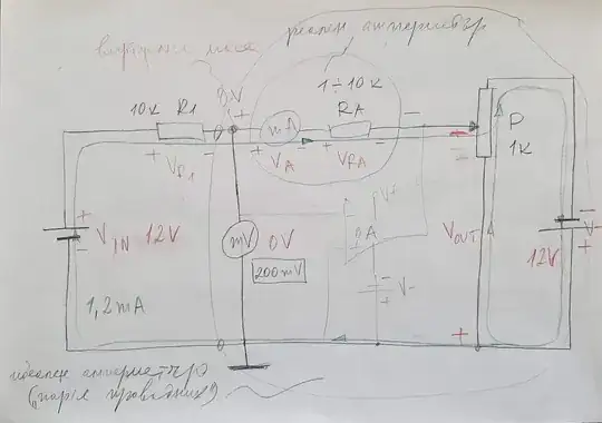
Fig. 2. "Ideal" ammeter (a rough sketch)
Now a new idea is popping up - to use the compensating voltage as an output. For this purpose, we connect a voltmeter (ADC) to this source. The benefits are obvious: first, an imperfect voltmeter will not divert current; second, this is a grounded voltage. Well, it is negative… but sometimes it is desirable.
All the inverting op-amp circuits are based on this idea (aka "virtual ground"). Transimpedance amplifier is the simplest example.
See also my stories about the op-amp ammeter in ResearchGate and Circuit-fantasia. The next RG story about transimpedance amplifier is a further development of this idea.
Generalization
It is interesting to see that the idea of the "ideal" ammeter is the well-known Miller effect. The idea behind the "ideal" voltmeter is added as a dual concept in Miller theorem.


