1

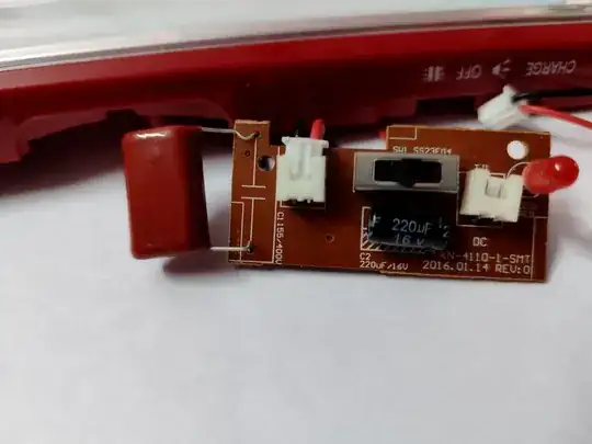
I'm trying to understand this circuit taken from a rechargeable flashlight. There's a 4V sealed lead-acid battery (not shown in the images) that gets charged when you connect the flashlight to 230V AC. The battery then powers the two LED modules thru a three-way switch.

Torch circuit - Front Torch circuit - Back

I see a couple of capacitors, a few resistors, and a small chip marked MB10F. I don't see any coil, transformer, transistor (may be inside the chip?) or heat sink.

How does this circuit work? How does it convert AC to DC to charge the battery?
  • 2
    Capacitive dropper (red thing hanging off the board) + bridge rectifier (SMD on the back side). Probably a Zener diode somewhere to limit the peak voltage too. – winny Apr 15 '22 at 15:57
  • 1
    I suggest that you trace the circuit out and draw a schematic using the schematic tool (CircuitLab) built into this site. – Kuba hasn't forgotten Monica Apr 15 '22 at 16:01
  • I feel stupid. That MB10F is indeed the bridge rectifier! https://www.diodes.com/assets/Datasheets/MB10F_LS.pdf What does that Capacitive dropper do? @winny – Ananth Pattabiraman Apr 15 '22 at 16:06
  • 1
    Google 'capacitive dropper circuit' or similar, it's all explained in detail there already. – TonyM Apr 15 '22 at 16:51
  • @AnanthPattabiraman - Hi, In addition to the question linked as a duplicate, there are other previous questions e.g. [here](/q/5572) and [here](/q/555659) discussing this type of power supply. (Your example may not have a zener diode seen in some others, and it may rely on the load from charging the battery to limit the output voltage.) If you review those questions, and the search suggestions given by other site members, and then have a very specific question, you can ask it separately. Thanks. – SamGibson Apr 15 '22 at 17:03

0 Answers0