You have two coils with a common. (+) goes to common then (-) goes to the other end of either coil. There's no singular "load" coil as you show. I won't investigate why the circuit may not work as you don't show any actual circuit diagrams of the assembled circuit, nor any pictures. So I have no idea what exactly did you do. I just assume it's all unnecessary anyway.
To drive the common, you can use a Sziklai pair as a top-side driver. No need for a MOSFET. Nothing wrong with MOSFETs, just that there is enough variety between the types that there's no common circuit that would work with all. Whereas with bipolar transistors, that's not a problem, and most any jellybean part rated at 300mA minimum will work just fine.
Two GPIOs per Segment
A low-side driver like a ULN2003 will do the job for set/reset as suggested in one of the comments to your other question.
The inputs will work fine from 3.3V outputs, so if you only used GPIO expanders to get 5V output - that is unnecessary.

simulate this circuit – Schematic created using CircuitLab
The circuit above simulates in real time. Click on any of the "⓪"/"①" input states to highlight them, then use Space to toggle them. The current meters will update to show which coil is energized.
To eliminate the high pulse currents, the segments should not be all switched at once. Operate only one segment at a time. The firmware should do as follows:
- For each digit:
- Enable the digit.
- For each segment.
- Strobe set or reset for T1.
- Wait T2.
- Disable the digit.
- Wait T3.
Implemented in Python, assuming no GPIO expanders, it'd look something like this:
import RPi.GPIO as GPIO
import time

ms = 0.001
T1 = 100*ms  # set/reset strobe
T2 = 10*ms   # inter-segment delay
T3 = 10*ms   # inter-digit delay

PIN_DIGIT = [1,2,3,4]
PIN_SEGMENT_SET = [5,6,7,8,9,10,11]
PIN_SEGMENT_RESET = [12,13,14,15,16,17,18]

FONT = {
 ' ': [0, 0, 0, 0, 0, 0, 0],
 '0': [1, 1, 1, 1, 1, 1, 0],
 '1': [0, 1, 1, 0, 0, 0, 0],
 '2': [1, 1, 0, 1, 1, 0, 1],
 '3': [1, 1, 1, 1, 0, 0, 1]
 # ...
}

def display_init():
  GPIO.setmode(GPIO.BOARD)
  for p in PIN_DIGIT + PIN_SEGMENT_SET + PIN_SEGMENT_RESET:
    GPIO.output(p, False)
    GPIO.setup(p, GPIO.OUT)

def display_update(text: str=""):
  N_digits = len(PIN_DIGIT)
  text = text.ljust(N_digits)

  for p_digit, char in zip(PIN_DIGIT, text):
    GPIO.output(p_digit, True)
    glyph = FONT.get(char, FONT[' '])
    for seg, p_set, p_reset in zip(glyph, PIN_SEGMENT_SET, PIN_SEGMENT_RESET):
      GPIO.output(seg and p_set or p_reset, True)
      time.sleep(T1)
      GPIO.output(p_set, False)
      GPIO.output(p_reset, False)
      time.sleep(T2)
    GPIO.output(p_digit, False)
    time.sleep(T3)

def display_shutdown():
  for p in PIN_DIGIT + PIN_SEGMENT_SET + PIN_SEGMENT_RESET:
    GPIO.setup(p, GPIO.IN)
  GPIO.cleanup()

if __name__=="__main__":
  display_init()
  display_update("4242")
  display_shutdown()
The GPIO expander will require modifications to pin access, but the general code flow would remain.
One GPIO per Segment
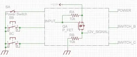
To save on GPIO pins, you can use a tri-state driver circuit, so that when the GPIO pin is switched to an input, neither SET nor RESET coils are driven.
You'll need only 4+7=11 GPIO outputs for the entire display that way. Given that transistors and resistors cost nothing compared to GPIO expanders, and GPIO expanders may be out of stock, the discrete driver is not the worst thing in the world :)
simulate this circuit
The circuit above simulates in real time. Click on any of the "⓪"/"①" input states to highlight them, then use Space to toggle them. Click on the switch SW1 to select it, then use space to toggle the GPIO direction. The current meters will update to show which coil is energized.
The firmware would then act as follows:
- For each digit:
- Enable the digit.
- For each segment.
- Set segment pin to output. Drive HI or LO as per segment status.
- Wait T1.
- Set segment pin to input to disable the segment driver.
- Wait T2.
- Disable the digit.
- Wait T3.
Implemented in Python, it'd look something like this:
import RPi.GPIO as GPIO
import time

ms = 0.001
T1 = 100*ms  # set/reset strobe
T2 = 10*ms   # inter-segment delay
T3 = 10*ms   # inter-digit delay

PIN_DIGIT = [1,2,3,4]
PIN_SEGMENT = [5,6,7,8,9,10,11]

FONT = {
 ' ': [0, 0, 0, 0, 0, 0, 0],
 '0': [1, 1, 1, 1, 1, 1, 0],
 '1': [0, 1, 1, 0, 0, 0, 0],
 '2': [1, 1, 0, 1, 1, 0, 1],
 '3': [1, 1, 1, 1, 0, 0, 1]
 # ...
}

def display_init():
  GPIO.setmode(GPIO.BOARD)
  for p in PIN_DIGIT:
    GPIO.output(p, False)
    GPIO.setup(p, GPIO.OUT)
  for p in PIN_SEGMENT:
    GPIO.setup(p, GPIO.IN)

def display_update(text: str=""):
  N_digits = len(PIN_DIGIT)
  text = text.ljust(N_digits)

  for p_digit, char in zip(PIN_DIGIT, text):
    GPIO.output(p_digit, True)
    glyph = FONT.get(char, FONT[' '])
    for seg, p_seg in zip(glyph, PIN_SEGMENT):
      GPIO.setup(p_seg, GPIO.OUT)
      GPIO.output(p_seg, seg)
      time.sleep(T1)
      GPIO.setup(p_seg, GPIO.IN)
      time.sleep(T2)
    GPIO.output(p_digit, False)
    time.sleep(T3)

def display_shutdown():
  for p in PIN_DIGIT:
    GPIO.setup(p, GPIO.IN)
  GPIO.cleanup()

if __name__=="__main__":
  display_init()
  display_update("4242")
  display_shutdown()
