15

I can't wrap my head around how the SR Latch works. Seemingly, you plug an input line from R, and another from S, and you are supposed to get results in Q and Q′.

However, both R and S require input from the other's output, and the other's output requires input from the other other's output. What comes first the chicken or the egg??

When you first plug this circuit in, how does it get started?

SR Latch

CodyBugstein
  • 435
  • 2
  • 5
  • 12
  • 1
    I finally found a really fantastic answer in the book [But How Do It Know](http://books.google.ca/books?id=-XGAPeVhRs4C&pg=PA9&source=gbs_toc_r&cad=4#v=onepage&q&f=true). You can see it at the link on page 24. – CodyBugstein Apr 16 '13 at 04:43
  • For the better understanding of SR Latch thoroughly and how it behaves for the different inputs like 00, 01, 10 and 11 check this video out. www.youtube.com/watch?v=VtVIDgilwlA‎ –  Jan 12 '14 at 06:57

5 Answers5

6

A perceptive question. In fact, if you build this latch in a simulation program, it will indeed show you that it can't predict what state it will start in:

RS latch with NOR gates, most signals are colored RED for "unknown"

But if you set one of the inputs high (those are pushbuttons on the left), the signal will propagate through (remember, 1 OR [anything] equals 1) and the circuit will latch that state:

Same latch; one input is high; the lines all turn light or dark green

These are NOR gates, so the inverted output goes low when either input is high. The program I used is Logisim. It is small, and I recommend it for starting out. Logic compilers (FPGA and everything else) love to complain about uninitialized states. This was a great first example.

Now, I know that in real life, the circuit will randomly latch into one or the other state on its own. Many others have pointed that out. But sometimes, it's important that it reliably start in one state or another, and that's what all the warnings are about.

gbarry
  • 8,615
  • 21
  • 31
  • Thanks for the great explanation.. If I get you right, when plugged in, the circuit starts off in some random state? – CodyBugstein Mar 22 '13 at 04:56
  • @Imray I would not use the phrase "random state" but "undefined state". It could randomly choose, it could be the same thing every time, the important thing is you don't know and don't care. All you need to do is realize you must initialize the latch (by pulsing R or S high briefly) before you start relying on the output. – Scott Chamberlain Mar 22 '13 at 14:24
  • I just reread your answer and understood things I previously missed. Great explanation! – CodyBugstein Apr 21 '13 at 23:36
5

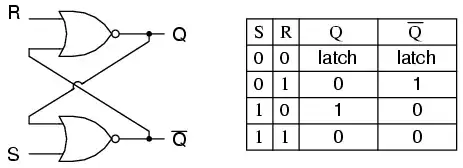
A flip-flop is implemented as a bi-stable multivibrator; therefore, Q and Q' are guaranteed to be the inverse of each other for all inputs except S=1, R=1, which is not allowed. The excitation table for the SR flip-flop is helpful in understanding what occurs when signals are applied to the inputs.

S R  Q(t) Q(t+1)   
----------------
0 x   0     0       
1 0   0     1   
0 1   1     0   
x 0   1     1   

The outputs Q and Q' will rapidly change states and come to rest at a steady state after signals have been applied to S and R.

Example 1: Q(t) = 0, Q'(t) = 1, S = 0, R = 0. 

State 1: Q(t+1 state 1)  = NOT(R OR Q'(t)) = NOT(0 OR 1) = 0
         Q'(t+1 state 1) = NOT(S OR Q(t)) =  NOT(0 OR 0) = 1

State 2: Q(t+1 state 1)  = NOT(R OR Q'(t+1 state 1)) = NOT(0 OR 1) = 0
         Q'(t+1 state 2) = NOT(S OR Q(t+1 state 1))  =  NOT(0 OR 0) = 1     

Since the outputs did not change, we have reached a steady state; therefore, Q(t+1) = 0, Q'(t+1) = 1.


Example 2: Q(t) = 0, Q'(t) = 1, S = 0, R = 1

State 1: Q(t+1 state 1)  = NOT(R OR Q'(t)) = NOT(1 OR 1) = 0
         Q'(t+1 state 1) = NOT(S OR Q(t))  = NOT(0 OR 0) = 1


State 2: Q(t+1 state 2)  = NOT(R OR Q'(t+1 state 1)) = NOT(1 OR 1) = 0
         Q'(t+1 state 2) = NOT(S OR Q(t+1 state 1))  =  NOT(0 OR 0) = 1     


We have reached a steady state; therefore, Q(t+1) = 0, Q'(t+1) = 1.


Example 3: Q(t) = 0, Q'(t) = 1, S = 1, R = 0

State 1: Q(t+1 state 1)  = NOT(R OR Q'(t)) = NOT(0 OR 1) = 0
         Q'(t+1 state 1) = NOT(S OR Q(t)) =  NOT(1 OR 0) = 0

State 2: Q(t+1 state 2)  = NOT(R OR Q'(t+1 state 1)) = NOT(0 OR 0) = 1
         Q'(t+1 state 2) = NOT(S OR Q(t+1 state 1))  = NOT(1 OR 0) = 0     

State 3: Q(t+1 state 3)  = NOT(R OR Q'(t+1 state 2)) = NOT(0 OR 0) = 1
         Q'(t+1 state 3) = NOT(S OR Q(t+1 state 2))  = NOT(1 OR 1) = 0     

We have reached a steady state; therefore, Q(t+1) = 1, Q'(t+1) = 0.


Example 4: Q(t) = 1, Q'(t) = 0, S = 1, R = 0

State 1: Q(t+1 state 1)  = NOT(R OR Q'(t)) = NOT(0 OR 0) = 1
         Q'(t+1 state 1) = NOT(S OR Q(t)) =  NOT(1 OR 1) = 0

State 2: Q(t+1 state 2)  = NOT(R OR Q'(t+1 state 1)) = NOT(0 OR 0) = 1
         Q'(t+1 state 2) = NOT(S OR Q(t+1 state 1))  = NOT(1 OR 1) = 0     

We have reached a steady state; therefore, Q(t+1) = 1, Q'(t+1) = 0.


Example 5: Q(t) = 1, Q'(t) = 0, S = 0, R = 0

State 1: Q(t+1 state 1)  = NOT(R OR Q'(t)) = NOT(0 OR 0) = 1
         Q'(t+1 state 1) = NOT(S OR Q(t)) =  NOT(0 OR 1) = 0

State 2: Q(t+1 state 2)  = NOT(R OR Q'(t+1 state 1)) = NOT(0 OR 0) = 1
         Q'(t+1 state 2) = NOT(S OR Q(t+1 state 1))  = NOT(0 OR 1) = 0     

We have reached a steady; state therefore, Q(t+1) = 1, Q'(t+1) = 0.


With Q=0, Q'=0, S=0, and R=0, an SR flip-flop will oscillate until one of the inputs is set to 1.

    Example 6: Q(t) = 0, Q'(t) = 0, S = 0, R = 0

    State 1: Q(t+1 state 1)  = NOT(R OR Q'(t)) = NOT(0 OR 0) = 1
             Q'(t+1 state 1) = NOT(S OR Q(t)) =  NOT(0 OR 0) = 1

    State 2: Q(t+1 state 2)  = NOT(R OR Q'(t+1 state 1)) = NOT(0 OR 1) = 0
             Q'(t+1 state 2) = NOT(S OR Q(t+1 state 1))  = NOT(0 OR 1) = 0     

    State 3: Q(t+1 state 3)  = NOT(R OR Q'(t+1 state 2)) = NOT(0 OR 0) = 1
             Q'(t+1 state 3) = NOT(S OR Q(t+1 state 2)) =  NOT(0 OR 0) = 1

    State 4: Q(t+1 state 4)  = NOT(R OR Q'(t+1 state 3)) = NOT(0 OR 1) = 0
             Q'(t+1 state 4) = NOT(S OR Q(t+1 state 3))  = NOT(0 OR 1) = 0     
    ...


As one can see, a steady state is not possible until one of the inputs is set to 1 (which is usually handled by power-on reset circuitry).

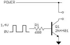
If we examine simplest implementation of an SR flip-flop (see http://en.wikipedia.org/wiki/File:Transistor_Bistable_interactive_animated_EN.svg), we discover that it is composed of two bi-polar junction transistors (BJTs) and four resistors (replace the SPST toggle switches to ground with SPDT switches that can switch the set and reset lines between ground potential and V+). The BJTs are configured as common emitter inverters. The collector (output) of each transistor is fed back into the base (input) of the opposite transistor. The input S is wire-ORed with the output of the BJT whose collector connection serves as the output Q (the junction of R1/R3). The input R is wire-ORed with the output the BJT whose collector connection serves as the output Q' (the junction of R2/R4).

When the circuit first powers up, neither transistor is forward-biased into the saturation region for a tiny fraction of a second, which means that both Q and Q' are at logic level 1. The voltage available at each collector is fed to the base of the opposite transistor, which causes it to become forward biased into the saturation region. The transistor that becomes forward-biased first will start conducting current first, which, in turn, will cause a voltage drop to occur across its collector resistor, setting its output to logic level 0. This drop in collector voltage will prevent the opposite transistor from becoming forward-biased; therefore, setting the initial state of the flip-flop. It’s basically a hardware race condition that leads to an unpredictable outcome.

bit-twiddler
  • 161
  • 5
  • Can you the circuit animation at the link provided, but in more simple terms? I'm taking a beginner undergrad course – CodyBugstein Apr 21 '13 at 23:38
3

Like you said, it's undefined. In practice there are transients or quirks which should put the latch into a certain state, but there is no guarantee which state it will be in. This is caused by mismatched in the two gates which will define a given initial state (basically the circuit doesn't behave as a true digital SR latch but is a complex analog circuit as it is in real life). The initial output will be more or less random, either Q=1 and ~Q=0 or Q=0 and ~Q=1.

Barring explicit mention by a datasheet I would not rely on one state being chosen over the other as the actual init state can change between different parts in the batch, placement on a board, environmental factors (temperature/humidity/etc.), and aging (by no means a complete list of factors).

The best way to define a state is after startup assert either the set or reset to put the SR latch into a known state.

As a side note, in general SR latches asserting S and R at the same time will also result in undefined behavior and you're relying on similar voodoo to set the outputs (a real implementation may shut off both outputs, randomly toggle the two, toggle both outputs on, etc.). As supercat commented if one pin is unasserted before the other the SR latch can enter a known state because only one pin is being asserted. Other types of latches/flip flops may define a different behavior, for example JK flip-flops define asserting both pins to toggle the outputs (Q = ~Qprev, ~Q = Qprev).

helloworld922
  • 16,600
  • 10
  • 54
  • 87
  • But my question is, how can it ever be set to anything if both inputs rely on inputs that don't yet exist? It's like a case of "you lift me up into the air, then I'll lift you and we'll both be floating in the air" – CodyBugstein Mar 19 '13 at 19:09
  • 2
    @Imray - one side of the flip-flop always beats the other when freshly powered. It usually always powers up the same way due to slight timing mismatches but there are no guarantees on this type of device. – Andy aka Mar 19 '13 at 19:15
  • 1
    Exactly. It depends on an a phenomena of mismatch. You need to not think of both sides as being exactly the same. They're not. One of them is slower, the other faster, and this will cause one of them to turn on initially. – Gustavo Litovsky Mar 19 '13 at 19:18
  • Yes, I would rely on this mismatch behavior to ensure the initial state is "valid" (we don't get Q=~Q), but I would not rely on this behavior to ensure Q is always a certain state on startup since this can vary between parts in a batch or even change for the same part over temperature/time. Of course the datasheet may state otherwise, but in general I would not rely on it otherwise. – helloworld922 Mar 19 '13 at 19:20
  • It's pretty common that the behavior of a latch will be defined when both inputs are in the "active" state [high for a NOR latch; low for a NAND latch], *provided* that the one of the inputs goes inactive noticeably before the other. – supercat Mar 19 '13 at 22:02
  • It should behave as if just the last asserted input is being asserted if one input is unasserted before the other (assuming a long enough transition). I was mainly noting what happens while both set and reset are asserted at the same time, not what happens after. – helloworld922 Mar 19 '13 at 22:12
  • @helloworld922: The term "asserted" is sometimes used to refer to being driven low (which may be the active or inactive state), and is sometimes used to refer to being driven to an active state (which may be high or low). For a NAND-based SR latch, there would be no ambiguity, but for a NOR-based latch the term is ambiguous. Which meaning did you intend? – supercat Mar 22 '13 at 00:03
  • logically asserted (a.k.a. digital 1). – helloworld922 Mar 22 '13 at 04:17
2

Keep in mind that the gates are inverting. This provides a positive feedback loop. Assuming that both S and R are zero and one output is one, this one will feed back into the other gate to force the other output to zero. This way, the gates are in either of two stable states.

As soon as you set one of S or R to one, this will force the corresponding gate to output zero which, in turn, will force the other gate to output zero. Again, stable.

For example, initial state: S = 0, R = 0, Q = 0, Q# = 1. You now set S = 1. This will change the lower gate output (Q#) to 0. This 0 feeds into the upper gate, forcing that output (Q) to 1. This 1 feeds back to the lower gate. When you set S back to 0, the lower gate is still receiving the 1 from the other gate. This will keep the Q# output at 0.

If Q already is 1 and you set S to 1, both inputs to the lower gate are 1 and so there is no change.

DoxyLover
  • 7,876
  • 1
  • 18
  • 24
  • I don't understand how Q' can ever be one if there are no inputs that can ever actually execute. – CodyBugstein Mar 19 '13 at 19:56
  • Again, the stable state is only when ONE OF Q and Q# is one. If not, (e. g. on power up), the gates will quickly assume one of the two stable states, depending on the actual speed of the two gates and such. Once the gates are stable, you can use the two inputs to switch between the stable states. – DoxyLover Mar 19 '13 at 20:51
1

I think the important bit that you are asking about has to do with the fact that the latch powers up in an unknown state, so how do we ever get it into a known state. You need to remember that if either input to a NOR gate is a 1 then the output must be a 0, regardless of the state of the other input. So applying the SET or RESET input combinations will always force the latch into the set or reset state, regardless of the previous state of the latch.

Joe Hass
  • 8,447
  • 1
  • 29
  • 41
  • Yes you understand my question! However, I still don't feel answered with what you've written. Suppose the latch had never been plugged in, and suddenly, for the first time, x and y are plugged in. How could they have any effect on Q if they can't possibly get past the initial gates?? – CodyBugstein Mar 20 '13 at 01:40
  • I'm assuming that you mean that the R and S inputs get some values X and Y. If either X or Y is a one, then the output of that NOR gate _must_ be a 0...that's how NOR gates work. So that 0 feeds back to the other NOR gate, which presumably has a 0 for its input (if X is 1 then Y is 0, or vice versa). So now the second NOR gate has two inputs that are 0 and its output must be 1. The only situation where we can't say what will happen to Q and Q' is if both X and Y (meaning both S and R) are set to 0 right after the power is turned on. As others have noted, this is an unstable state. – Joe Hass Mar 20 '13 at 03:01