I intended to use the INA219 chip to read the 4-20 mA current loop of the industrial sensor for the automation project. the sensor voltage is 12 V, my first schematic was as follows:
The ground of the MCU and the sensor are the same. However when I connect the sensor, the INA chip always sends the same value and does not change with different sensor conditions, at first I've tried to change the regulation and calibration of the INA chip with regard to datasheet and library code, but also no big change.
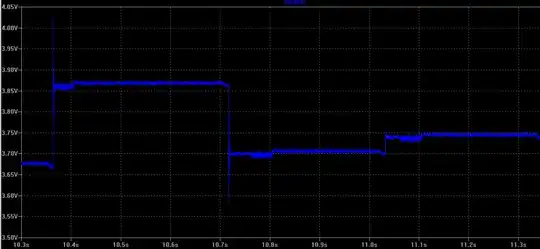
It seems the voltage of the shunt resistor reaches the maximum value of the voltage reference for analog measurement.
Some searching on the internet shows that some application uses the following schematic for sensor connection, but I still don't figure out how the voltage across the shunt resister remains unchanged with different voltage input. Also, I ran the test to manually create the fixed current with the power supply.
My experiment consists of fixing known resister (180) which series with shunt resistor and power supply set to a specific value (.86 V to 3.3 V) to create the specific current in the path, but same result, no change with different voltage input which theoretically has different current on the shunt resistor.
Any tips to solve this mysterious behavior really appreciated.

