16

I know that switching logic values causes power dissipation but I could never understand why.

Is it because transistors need to be turned on each time we want to charge/pull up a node and discharge/pull down a node? Is this power consumed by the transistor responsible for the switching multiplied by the activity factor and frequency called the dynamic power? Is power dissipation just another word for power "consumed"?

NVZ
  • 107
  • 1
  • 5
penguin99
  • 829
  • 1
  • 8
  • 22
  • 5
    See [Landauer's Principle](https://en.m.wikipedia.org/wiki/Landauer%27s_principle) and [The Physics of Forgetting: Thermodynamics of Information at IBM 1959–1982](https://direct.mit.edu/posc/article-pdf/24/1/112/1790128/posc_a_00194.pdf) for a foundational answer. Everything else is just detail. – jonk Mar 31 '22 at 06:44
  • 16
    A "classical" explanation, not involving Landauer's principle or other arcane physics: No switching happens instantaneously. Because of this,, during the switch transition period neither voltage nor current across the switch will be zero, meaning net power will be dissipated by the switch during the cross-over. Of course there is also the energy needed to "throw" the switch, in the form of gate charge/discharge. – Bart Mar 31 '22 at 08:12
  • 1
    Switching results in current such that a voltage changes. Resistance is never zero, so until we have superconducting ICs, switching always consumes power (= I^2*R). – J... Mar 31 '22 at 16:25
  • 1
    Switching CMOS (or even just MOS) transistors causes current draw. That is not the special case. Using electronics should be expected to cause current draw. Using BJT transistors **ALWAYS** draw current regardless if it is switching or not switching. But the special case is that CMOS **does not draw power** if it is not switching. So using electronics **ALWAYS** cause power draw **EXCEPT** when a CMOS transistor is not changing voltage level -- THAT is the strange part – slebetman Mar 31 '22 at 18:39
  • 2
    Semi-related: [Modern Microprocessors A 90-Minute Guide!](https://www.lighterra.com/papers/modernmicroprocessors/) has a section on power, and how higher frequency needs higher voltage to switch fast enough to maintain correctness, so power scales approximately as frequency cubed, assuming voltage is adjusted to be just enough for the current frequency. This is a *consequence* of the CMOS switching details you're asking about, switching energy per CMOS gate scaling with V^2 as the energy in the capacitance, not an explanation, hence just commenting. – Peter Cordes Mar 31 '22 at 19:21
  • "Is power dissipation just another word for power "consumed"?" More or less, yes. Sometimes electronics has only 1 function, to dissipate excess power into heat without damaging the system. In which case we really prefer talking dissipation over consumption. Besides, if a frequency drive 'consumes' multiple kilowatt while giving most of it to the motor behind it, the amount it dissipates should be much lower than the amount it consumes. Consumption is ambiguous, dissipation is not. – Mast Apr 02 '22 at 10:05

8 Answers8

16

Consider a MOSFET switching.

Switching is a transient event, so losses are not usually modeled as "power". Each switching action dissipates a bit of energy. Then you multiply this by the switching frequency (or divide by the period), and you get the dissipated power, which is energy dissipated over one second.

In order to switch from "off" to "on" state, its gate needs to be charged to a suitable voltage, which involves both gate-source and gate-drain capacitance. The charge required is called "gate charge". The current to charge it comes from the driving circuitry, which has to expend a bit of energy to provide it. How much depends on the capacitance of the FET, and due to the gate-drain capacitance \$C_{gd}\$, its drain-source voltage \$V_{ds}\$. Basically, the driver switches a FET between VCC and the driven FET gate, this FET is resistive when it is on, and the gate current incurs resistive losses. When turning the driven FET off, its gate is shorted to ground with another driver FET, so that doesn't draw current from VCC and although power is dissipated in the driving FET, it doesn't count for the total energy budget. To switch a big power MOSFET quickly, the driving circuitry may have to provide quite a lot of current (several amps).

Then, as its gate charges up, the MOSFET does not go from "off" to "on" instantly. Between the two, there is a short interval where its gate voltage is rising (or falling) and the FET works in linear mode. In a buck converter, for example, the inductor current doesn't stop flowing during switching, it simply switches from the top FET to the diode (or the bottom FET). For example, when the top FET turns off, its drain voltage goes from near zero (when it was conducting) to the full supply voltage. During all this time, inductor current is still flowing through the FET, which dissipates power v.i, with i being roughly constant, and \$V\$ ramping from 0V to VCC. Only when the other FET (or the diode) turns on, does the inductor current stop flowing into the top FET, to flow into the other instead. This leads to a loss of energy in the FET, which is roughly half the product of switching time, \$V_{ds}\$, and \$I_d\$. Since it occurs twice on each period, you can calculate the switching energy loss per period as \$T_{switch} \cdot V_{ds} \cdot I_d\$.

The above applies mostly to power FETs, not to FETs in logic gates. The latter aren't driving inductors, so there is no inductor to force current through the FET as it turns off. Its gate still needs to be driven, but if there is no drain current, then there are no switching losses.

Then there is the load capacitance. There is always capacitance, so when your FET switches, it will bring the output voltage across the load from 0V to VCC and back. Every time, this charges and discharges the load capacitance, and that causes the same kind of losses as explained above when driving the FET gate.

bobflux
  • 70,433
  • 3
  • 83
  • 203
  • Thank you for your answer. I understand that going from an OFF to an ON state requires energy to bring the gate voltage up to a certain level, that is charging the gate to drain and gate to source capacitance. But for going from ON to OFF, wouldn't it be as simple as shutting off supply to the gate and discharging whatever was stored earlier at the gate capacitance? This wouldn't require using any energy right? – penguin99 Apr 03 '22 at 04:22
  • Yes, correct, to turn it off, the driver shorts gate to source to discharge the gate capacitance. That doesn't draw any power from VCC. – bobflux Apr 03 '22 at 06:11
  • So does only moving from an OFF to an ON state consume power? – penguin99 Apr 03 '22 at 23:59
  • Yes. The gate driver itself will consume a bit of power on both transitions for its own internal circuits, but the energy to charge the driven FET gate is only consumed when it turns on, not when it turns off. However, switching losses in the driven FET occur on both transitions if current through it is not zero. – bobflux Apr 04 '22 at 04:02
10

Let's focus on CMOS technology, which is the most widely used logic technology nowadays and it's fairly simple to understand.

The basic building block of CMOS gates is a structure that works as an inverter, with an NMOS and a PMOS acting as switches that turn on and off alternatively (Complementary MOS -- CMOS). Other gates are just more complicated set-ups of pairs of NMOS-PMOS switches.

So let's consider the basic inverter structure:

schematic

simulate this circuit – Schematic created using CircuitLab

There are two sources of energy loss in this circuit during switching:

  • The gates of the PMOS/NMOS must be charged/discharged to make the input switch state (and hence to make the inverter output to switch state). You can picture this process as an RC circuit charge-discharge cycle, where the R is the output resistance of whatever drives the gates.

  • During switching the voltage on the gates varies with finite speed, therefore there is a finite time interval during which neither the PMOS nor the NMOS is completely switched off (in ideal static conditions either one should be completely off and the other completely on). Hence the I0 current will be non-zero (this is called shoot-through) because the power rail will be "shorted" to ground with a relatively small resistance for a (hopefully) small amount of time. That's why it's dangerous to make a CMOS input float: it could reach an intermediate voltage level for which both MOSFETs are partially on, making I0 non zero continuously, with the risk of overheating and damaging the transistors.

Of course these small gulps of energy that get lost at every switching event become ever more relevant as the switching frequency increases and as the driving signal edges become slower (longer rise time).

8

Why does switching cause power dissipation?

Imagine you had a near-perfect switching transistor that needed no control energy to cause it to change from an open-circuit to a very-low-value "ohmic" closed circuit (or vice versa). There's no energy wasted in the driving of this transistor by definition.

Then, imagine that the transistor had to discharge a node from (say) 5 volts to 0 volts - imagine also that the node possessed no self-capacitance. This would then mean that no energy was needed to change the voltage on that node from 5 volts to 0 volts.

It also means that the node in question would take no energy to re-establish the 5 volts when the discharge transistor went open-circuit.

But, every node does have capacitance and, initially that capacitance is charged to 5 volts so, in order to discharge that node, you need to remove energy and convert it to heat in the very-low ohmic "on" resistance of that transistor. So, you have "burnt" energy and made it into heat and, when the transistor disengages, the node capacitance re-charges to 5 volts - to do so it has to take energy from the power rails to recharge the capacitance.

So, if this is repeated cyclically, you are taking energy from the power rails cyclically and converting that energy to heat.

Power is energy per second. Switching therefore causes power dissipation. If you do this switching at a low frequency the power is lower; if you do it at a high frequency, the power is higher.

Andy aka
  • 434,556
  • 28
  • 351
  • 777
6

My thoughts are in line with @Bart's comment, so I'll post what (hopefully) should be the thousand words:

nothing is perfect

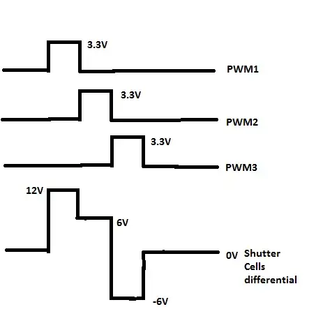
Consider V(a) and V(b) two waveforms that switch between 0 and 1. Since nothing happens instantaneously in nature, the transitions between the values takes a finite time. If one of them is a voltage and the other is the current, then the two, multiplied, will give the power. But when V(a)=1, V(b)=0, and vice versa, so when the multiplication happens during their maximum/minimum values, the power is zero. Therefore the only times when the power takes value is during transitions and, because the two quantities are ideal and linear, it takes the form x(1-x).

In rest, all the other answers have already explained at large with examples, and mentioned that nothing happens for free (you need work to make the switchings happen).

a concerned citizen
  • 21,167
  • 1
  • 20
  • 40
  • 1
    Came just to upvote the answer which had this type of plot - I was actually looking for voltage, current, and power through a single switch but that's the closest. – Mister Mystère Apr 04 '22 at 06:05
5

Besides the Landauer limit mentioned by @jonk, most real physical implementation of an irreversible state switch dissipate extra energy.

In a simple electronic system such as a flip flop or NOT gate, the state changed is caused by electrical charge current through resistive traces. Charge current flowing through a resistor generates heat. This heat is for the most part irrecoverable because the heat dissipation raises entropy.

These electronic systems also fundamentally require the resistance in order to function. If you remove all resistance from an electrical circuit, you would be left with an ever oscillating mesh of charge current. That means, without resistance, there can't be an irreversible state switch in a purely electronic system. This is also the essence of the above mentioned Landauer Limit. If you have two states that are distinct, there must be an energy barrier separating them, and overcoming the energy barrier dissipates the according energy amount.

tobalt
  • 18,646
  • 16
  • 73
  • It's not the resistance that dominates in CMOS circuits -- it's the capacitance. The total power consumption of a CMOS circuit is dominated by C.V.f, and is irrespective of the resistance of the CMOS devices (other than the relationship of FET resistance to gate charge required) – jp314 Apr 01 '22 at 17:24
  • @jp314 The crucial thing about CVf losses in this context here is, though: They occur because, and only because, the C *has to be* charged resistively. – tobalt Apr 01 '22 at 17:53
  • My point is that reducing the wiring resistance wouldn't change anything significant about the power dissipation -- it doesn't appear as a term in the equation: P=C.V.f. In theory you could use resonant switching and improve efficiency somewhat, but it's impractical. – jp314 Apr 01 '22 at 20:47
  • @jp314 Ah yes. Wiring resistance isn't really fundamental as mentioned in another comment. but the switch resistance is. with resonant switching and negligible resistance, you could forego CVf losses (like a SMPS), but you lose the determinism, so you can't process data. – tobalt Apr 02 '22 at 05:48
  • @tobalt if it's because of resistive charging of capacitors, it should be possible to decrease it by inventing a logic family driven by current sources, right? – user253751 Apr 02 '22 at 22:02
  • @user253751 Well a resistor (or a MOSFET channel) connected to a low impedance voltage rail *is* a current source. Anything that limits charging current (aka a current source) must be also resistive. I really think that the *requirement for resisance* is a direct consequence of Landauer's principle. – tobalt Apr 03 '22 at 04:30
  • @tobalt Yeah but we can also invent current source circuits that don't waste 50% of their power. An appropriately configured switching regulator can charge a capacitor with more than 50% efficiency. – user253751 Apr 03 '22 at 17:30
  • @user253751 No you can't charge a capacitor with more than 50% efficiency **if** by charging you mean that it attains a new *stable* DC voltage level. What an SMPS does is send current into caps and doesn't wait for this equilibrium, it toggles between different equilibrium levels faster than they can be achieved. This is the same as suggested by jp314 above. And as I explained, it works for an SMPS because you don't need to achieve stable deterministic voltage levels there. – tobalt Apr 03 '22 at 17:34
  • @tobalt uh... even if you do mean that by charging a capacitor (which isn't what those words mean) you can still do it with a current source: charge it for a while, then turn off the current source. – user253751 Apr 03 '22 at 18:06
  • @user253751 Then either the current source was resistive or was inductive and needed charging. I am inclined to believe that you can't get above 50% that way, but it is an interesting question. Maybe make a new one? You can read also this question and others: https://electronics.stackexchange.com/questions/487110/initial-current-value-in-capacitor-charging-circuit – tobalt Apr 03 '22 at 18:26
  • @tobalt except I don't misunderstand anything (about charging capacitors, that is; the idea that a current source could possibly improve efficiency *of switching* **was** wild speculation). Maybe you should ask a question about whether it's possible to charge a capacitor with >50% efficiency. – user253751 Apr 04 '22 at 10:18
  • @user253751 I did here: https://electronics.stackexchange.com/questions/614521/is-charging-a-capacitor-to-a-new-dc-voltage-fundamentally-50-lossy Your participation is welcome :) – tobalt Apr 04 '22 at 10:54
5

I think the other answers lack a calculation to show the true implications of power consumption in digital circuits.

For simplicity we can say transistors turn on / off when there's a high / low voltage at their input called the "gate". In order to stay on, there must be some capacitance here, \$C\$. In order to change the state of the transistor from off to on we must charge the voltage on this capacitance from \$0\$ to \$V\$ (where \$V\$ is the logic "high" in our circuit) and to change it from on to off we must discharge the voltage over this capacitance \$C\$ from \$V\$ to \$0\$.

We charge and discharge this capacitance using other transistors (Imagine these "driving" transistors as being the input from a previous logic gate, and the "driven" transistor is the next logic gate in the chain). When we want to charge the input capacitor a current flows from the source with a voltage of \$V\$, through the driving transistor, into the capacitor. This current flows, decreasing toward zero as the capacitance fills up.

How much energy did this turning on sequence use? Well there was some current flowing and there was a voltage across the driving transistor but as the capacitance filled up the current and the voltage across the driving transistor went to zero. Since \$P = IV\$, obviously there was some power dissipation over the transistor while the capacitor was charging, but there is no power once it's charged. This is what is meant by only "dynamic power" or "switching power" is consumed: it only takes power to charge and discharge this capacitor because we waste power by heating up the driving transistor a bit during this process.

So what's the total energy usage? Well energy during the charging cycle (assuming we decide to hold the gate on for an infinite amount of time before turning it off, a reasonable approximation) is \$\int_0^\infty P(t) dt\$ = \$\int_0^\infty I(t) V_t(t)dt\$ where \$V_t(t)\$ is the voltage over the transistor, and \$I(t)\$ is the current. But we don't really know the exact charging curve associated with the transistor or the exact voltage curve, so we want a simpler expression for this equation. To get this, realize that the capacitor and transistor are the only two elements in series from the supply to ground, and thus their voltages add to equal the supply power, \$V\$ (by Kirchoff's voltage law). Thus, \$V_t(t) = V - V_c(t)\$. Subbing into the equation: $$ E_{1/2 cycle} = \int_0^\infty I(t)(V-V_c(t)) dt = \int_0^\infty I(t)V dt - \int_0^\infty I(t) V_c(t) dt. $$

This latter integral is of course the total energy stored in the capacitor after infinite time has passed which we can call \$E_c\$. Thus, $$ E_{1/2 cycle} = \int_0^\infty I(t)V dt - E_c $$

What is this actually saying? It's saying the total power used in the circuit is the energy lost by the power source (\$E = \int_0^\infty I(t)V dt\$, simply the supply voltage times the supply current integrated to get supplied energy), minus the energy we're not wasting to dissipation and is being stored in the capacitor (\$E_c\$).

What happens when we reverse this process? Now all the energy stored in the capacitor gets dissipated across the driving transistor draining the capacitance. All the current flows in a loop back into the other end of the capacitor: the capacitor when draining here acts like a source. In this way it's obvious all the energy stored in the capacitor is now lost, dissipated across the draining transistor. So even though the power we spent charging the capacitor was not previously lost, it is lost now. So the total power lost in an a full on-off cycle increases by \$E_c\$:

$$ E_{tot} = \int_0^\infty I(t)V dt $$

We can find the current by remembering the current voltage relationship in the capacitor when it is fully charged from \$ 0\$ to \$V\$ as it is in it's initial cycle: \$ V = (1/C)\int_0^\infty I(t) dt\$. Rearranging this gives \$\int_0^\infty I(t) dt = CV\$. We can finally plug this into our total energy equation:

$$ E_{tot} = CV^2 $$

The equation for a capacitor charged to a voltage \$V\$ is known to be \$E_c=(1/2)CV^2\$, thus

$$ E_{tot} = 2E_c $$

Thus no matter what we do, no matter how we drive our transistors, the energy we waste each cycle is twice the energy we store on the gates of transistors during cycles. This is the nature of dynamic power - it only consumes energy to charge and discharge capacitors. To use less energy we can decrease the capacitance, or switch them on and off less.

Kevin Brant
  • 434
  • 3
  • 13
  • 1
    The integrals are overkill, I think. As you point out, we already know the energy in a capacitor is CV^2/2. Dumping this energy to ground through a transistor clearly dissipates that much energy as heat in resistance in the transistor and traces, because the energy has to go somewhere, and if not into an inductor then it's dissipated. By symmetry, charging a capacitor is just like discharging a negative voltage (relative to the +V supply). So an energy argument gets us there with much less math. Although it is still useful to think through the details of a half-cycle of current flow. – Peter Cordes Apr 03 '22 at 02:02
  • 1
    I was trying to think like that when writing this answer but couldn't quite see it on the charging cycle. It seems ridiculously simple in retrospect, but honestly I never realized the energy dissipation symmetry between a charging and discharging capacitor until now. That's for the tip. I definitely think it would be worth adding to my answer (once I find the time). – Kevin Brant Apr 03 '22 at 16:59
2

Simple answer, and not too accurate.

Transistors need continuous current in their base to remain ON, so they consume energy while they are in ON state. When you turn them off, they simply stop to consume energy. So continuous switching is not a major cause of energy dissipation in this case (but there are other losses anyway).

BUT for switching applications (logic circuits and power circuits), MOSFETs are used instead of transistors. A mosfet consumes very little energy in its gate. Its gate is like a capacitor: you charge the capacitor (gate) and the mosfet turns ON, you discharge the gate and the mosfet turns off. Every time you discharge the gate, you waste energy, and if you do that many many times per second, that wasted energy becomes important. Think at a CPU with so many mosfets, turned on and off with frequencies of a few gigahertz, and you can imagine why a CPU consumes so much power.

Philosophic note: I said energy is wasted when you turn off the gate, because normally this is done by dissipating that energy into a resistor which converts the energy in heat. When you push energy in the gate, this energy is not yet wasted because it is stored into the gate capacitor, but I am not aware of a system able to get that energy back in order to use it for something useful. May be this will be the next big improvement in digital electronics? :-)

--- UPDATE --- It seems that nobody thinks that a resistor in series to the gate is often necessary, surely when the driven mosfet is a power mosfet, like those used in H-bridges. The third result from a search on the internet leaded to this document by Toshiba which, at point 2.1 "Basic drive circuit" shows the gate resistor with the associated explanation:

basic gate driver

Another example, taken from a real board (a brushless controller), which also shows the value of the resistor (the driver is a FAN7382:

enter image description here

Now, I agree that often there is no gate resistor. This is a particular case where the gate resistor is near to zero, but anyway the stored charge in the gate must be dissipated when driving the mosfet off. If the driver of the gate can withstand the peak current and/or the total power, taking also in account the frequency of the switching, then no resistor is needed.

Finally, an interesting question with answers is in this very site electricalengineering.

  • 2
    *'When you push energy in the gate, this energy is not yet wasted because it is stored into the gate capacitor, but I am not aware of a system able to get that energy back in order to use it for something useful. May be this will be the next big improvement in digital electronics? :-)'* No. See my last paragraph for context. Indeed pushing charge into the gate cap **and keeping it there** (i.e. no oscillation) means that exactly half the energy is already dissipated in some resistance. – tobalt Mar 31 '22 at 07:49
  • @tobalt in your answer you mention "resistive traces", and I agree with you. But I am referring to resistors used to discharge the gates, which dissipate much more energy. And they are needed, they are not a collateral effect (resistance) of a conductor. In the last paragraph you then say "require resistance in order to function", and that is precisely what I mean. If you could discharge gates without resistor, you would save energy. – linuxfan says Reinstate Monica Mar 31 '22 at 08:05
  • I agree the trace resistance is not fundamentally needed and would be the "extra dissipation" I mention. But the switch resistance and switch dissipation is fundamentally important for the function. – tobalt Mar 31 '22 at 08:35
  • @linuxfansaysReinstateMonica There are no resistors used to discharge gates. It is "resistive traces" both ways. – user253751 Apr 01 '22 at 10:34
  • @user253751, thank you for the info. I have updated my answer, please take a look. – linuxfan says Reinstate Monica Apr 01 '22 at 13:28
  • @linuxfansaysReinstateMonica In this case the resistor still dissipates energy both ways. – user253751 Apr 01 '22 at 14:18
  • @user253751: true. But when you charge the gate, the dissipation is a collateral effect, not an effect you really want. You use the resistor to limit EMI, or to protect the circuit, or to slow down the activation of the mosfet. Instead, when discharging, you dissipate the stored energy just because there is no other way to use it again, so you "really want" to trash that energy. – linuxfan says Reinstate Monica Apr 01 '22 at 14:37
  • @linuxfansaysReinstateMonica It is a collateral effect both ways. Remember the equations are pretty much symmetric outside of the transistor itself. Adding positive charge to an negatively charged gate, and adding negative charge to a positively charged gate, are symmetric. – user253751 Apr 01 '22 at 14:43
  • "...MOSFETs are used instead of transistors." Are you aware that the "T" in "MOSFET" means "Transistor"? I guess you are identifying transistors with BJTs (bipolar transistors). BJTs are just one type of transistors (the first commonly available commercially), but by far not the only one: MOSFETs, JFETs, IGBTs are all transistors. You should get your terminology right to avoid misleading people reading your answer (especially newbies). – LorenzoDonati4Ukraine-OnStrike Apr 11 '22 at 20:40
  • @LorenzoDonatisupportUkraine, I am aware of what the acronym MOSFET means. I focus on the fact that transistors amplify current, while mosfets do not. That "T" in the acronym does not imply that a mosfet is a normal transistor and, in fact, the terminals have different names (BCE vs GDS). Think at SSRs, you know what "R" means. Anyway if you want to use transistors to do heavy switching, nobody prevents you. – linuxfan says Reinstate Monica Apr 12 '22 at 05:40
  • @linuxfansaysReinstateMonica I'm not arguing against your explanation, I'm pointing out your use of terminology, which is incorrect. There is no "normal transistor". Transistor is an umbrella term. You imply that BJTs are "normal" whereas MOSFETs are special. This could have been true ***statistically*** in the 70s of last century. Nowadays, however, MOSFETs are *by far* the most common type of transistor in use, and it has been like this for almost two decades *at least* (again, statistically speaking). ... – LorenzoDonati4Ukraine-OnStrike Apr 12 '22 at 23:47
  • @linuxfansaysReinstateMonica ... In digital applications, if we count the number of single devices produced, MOSFETs beat BJTs by a billion to 1 or more! Even in analog applications MOSFETs are probably the most common type of transistor (although BJTs are still widely used there). – LorenzoDonati4Ukraine-OnStrike Apr 12 '22 at 23:48
  • @linuxfansaysReinstateMonica BTW, historically MOSFETs were invented before BJTs, but the process for producing them was not perfected until much later, so BJTs have taken the lead role during the 60s and the 70s, supporting the digital revolution. That led to the usage of the term "transistor" to mean "BJTs". Today using the term "transistor" meaning "BJTs" is like calling a capacitor a "condenser". It's just obsolete terminology usage. – LorenzoDonati4Ukraine-OnStrike Apr 12 '22 at 23:59
2

I think this question needs a simple answer...

Moving a coulomb of electrons (that's 6*1018 of them) from ground to, say, the 5V rail spends 5 joules of energy.

An FET/MOSFET/JFET/etc transistor is turned on or off by moving some electrons from ground into the gate or moving some electrons from the gate into the positive rail. Each cycle, therefore, spends a little bit of energy and the more often you do this the faster you spend that energy. Rate of energy spend is power spend.

A BJT transistor is turned on by letting some electrons leak from ground, through the emitter-base junction, to the positive rail. These kinds of transistors (not used in computers anymore) spend energy continuously while they are on.

To answer your other questions:

  1. Yes, the "dynamic power" dissipated by a CMOS/MOSFET circuit is the the cost of all those little gate charge/discharge cycles. Note that this isn't all spent in a particular component. If you switch slowly, then it's mostly spent in the switch that is controlling the transistor (as answers above explain). The faster you switch, the more of it gets spent in the wires or in the transistor being controlled. The amount of energy spent is unchanged by this, though.

  2. Power that is dissipated is lost as heat. That doesn't include power output in useful forms like mechanical work. For a logic chip, power dissipated in the chip doesn't include power actually output from the chip, although most often this will just be dissipated somewhere else.

Matt Timmermans
  • 1,358
  • 6
  • 7
  • *"If you switch slowly, then it's mostly spent in the switch that is controlling the transistor (as answers above explain). The faster you switch, the more of it gets spent in the wires or in the transistor being controlled. **The amount of energy spent is unchanged by this, though.**"* Wrong! If you switch a CMOS pair slowly the energy dissipated will increase because of shoot-through (unless there are specific countermeasures, like a Schmitt trigger input). – LorenzoDonati4Ukraine-OnStrike Apr 11 '22 at 20:46
  • Yes, that's a good point. There is waste when you pull up and down at the same time. – Matt Timmermans Apr 11 '22 at 22:21