4

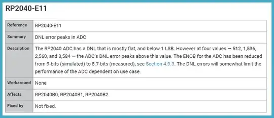
The errata of RP2040 datasheet mentions a peak DNL error in some values. I'm a newbie on ADCs but I always thought the DNL error is usually the same all over the range. Here itsays that it "peaks" in some values with a large error:

RP2040 DNL error

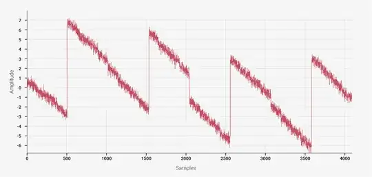
There's another figure that plots the DNL error per samples. The peaks correspond to 1/8 Vref, 3/8 Vref, 5/8 Vref, 7/8 Vref:

DNL error plot

Let's say we have a signal which rises from 0V to Vref and ADC values range from 0 to 4095 for a 12-bit ADC. What happens when we reach the values mentioned as "DNL error peaks"?

JRE
  • 67,678
  • 8
  • 104
  • 179
Tirdad Sadri Nejad
  • 1,735
  • 1
  • 9
  • 17
  • Very weird. It seems a problem with only 2 bits ... Very bad design, probably, adc ... – Antonio51 Mar 27 '22 at 10:16
  • 4
    See this https://pico-adc.markomo.me/INL-DNL/ and this https://www.hackster.io/news/raspberry-pi-confirms-it-is-investigating-a-flaw-in-the-raspberry-pi-pico-rp2040-adc-95c393b55dfb – Antonio51 Mar 27 '22 at 10:21

2 Answers2

8

The short answer to "What happens when we reach the values mentioned as 'DNL error peaks'" is you will see the ADC linger on those codes for longer than you would expect, the "bucket" for those codes is wider than the buckets for other codes.


Here is a plot of the total error of the ADC on a Raspberry Pi Pico, this is the number of LSBs off the center of the bucket for that ADC input is from that of an ideal ADC. You can see that those codes are much much wider, pushing out the values from the codes around them.

RP20f0 Total Error

Why and how is the above plot different from the INL curve in the datasheet?

Why is the above curve different from the curve that you see in the datasheet for INL? It all has to do with how the INL is measured. The INL is derived from a measurement of the DNL, which in turn is measured with the sine sweep method explained on my website. The sine sweep method discards the gain errors, and only directly measures the ratios of the ADC code sizes. The DNL is in turn integrated to give the INL (Integral Nonlinearity), discarding the offset.

The INL is (almost always) a best-fit line through the total error, as a result of the standard measurement methods. That's why you typically see the sharp vertical lines and slow rises centered around zero error.

RP2040 datasheet INL Curve: Pico ADC INL


I was one of the users that brought this issue to light, you can read about my measurements on my website here.

SamGibson
  • 17,231
  • 5
  • 37
  • 58
Mark Omo
  • 487
  • 6
  • 20
3

What happens when we reach the values mentioned as "DNL error peaks"?

As you linearly increase the voltage, the digital readout jumps as you reach those DNL error peaks. It can jump in two ways:

  • it decreases, in which case you will get the same digital output value for two different input voltage levels,
  • it increases, in which case you have missing codes: some digital output values cannot be obtained at all, no matter what the voltage is.

One workaround I've found reliable is to sample the signals twice, the second time with a small offset voltage added, e.g. by turning on a current source that dumps current into the output impedance of the voltage source used. That way, if you determine that the reading is close to one of the DNL peaks, you instead use the other reading, and subtract the offset. The offset can be continuously calibrated: for each pair of readings (one with, one without offset), take their difference and use it to update a digital low pass filter, whose output is then the estimate of the offset you're adding on the analog side of things. The update of this filter is suppressed in the neighborhood of the DNL peak.

Essentially you're losing half the ADC sampling rate if the inputs are within the error bands of the DNL peaks (i.e. within say +/-16 counts of each peak). Otherwise, you can use the offset samples, after offset removal, to reduce the noise level of the signal by averaging both of them.

There are many ways to implement the offset addition of course. Use whatever works without corrupting the signal.