13

I'm observing a strange behaviour in some of my PCBs: they start working only when I spray isopropyl alcohol on them (or, to be more specific, the boost converter starts doing his job only after I spray it with alcohol, while connected to a power supply).

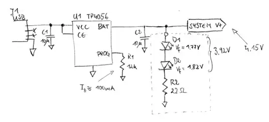
Let me explain this further: given this schematic, if I apply 3.8 volts (with a bench power supply at the moment, but I tried with a lithium polymer battery, too) to the "BATT" connectors, I expect get 3.3 V out of the TPS61201, but I get 0 V.

Schematic

At this point, if I spray some isopropyl alcohol (IPA) over the general area where the TPS61201 sits, I get 3.3 V out of it, and it will keep on supplying 3.3 V until I shut the bench supply off (let it run for more than 5 hours).

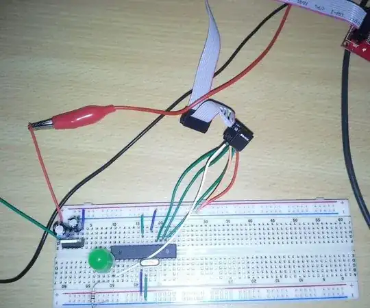
I'm observing this behavior in the last two PCBs I've soldered, but the three I soldered before these worked flawlessly, so I'm inclined to think that the flaw lies with my handywork (I am currently using a hot air station to solder the components in question), but I can't explain the strange behavior with the alcohol. Any idea why this might happen? Here is a photo of the soldered TPS61201:

Soldered TPS61201

If it may help, here is a screen of the board's layout.

Board's layout.

I've done some probing around the converter, as suggested, and here are my findings:

When the converter "doesn't work":

  • Vin: 3.9 V
  • EN: 3.9 V
  • PS: 3.9 V
  • FB: 0 V
  • Vout: 0 V
  • UVLO: ~272 mV

After a quick spray:

  • Vin: 3.9 V
  • EN: 3.9 V
  • PS: 3.9 V
  • FB: 3.35 V
  • Vout: 3.35 V
  • UVLO: ~272 mV

I've ordered a can of freeze spray for further testing and I'm thinking of a way to measure my board temperature around the converter, to rule out a thermal protection problem.

I'm trying to "digest" all the suggestions, but it may take me some time, for my background is lacking in the field, so bear with me.

Ok, maybe I find the issue, thanks to @TonyStewartEE75 and @BruceAbbott answer and comment.

I didn't understand the UVLO hysteresis at all: according to the datasheet the rising UVLO voltage (that is, if I get this correctly, the minimum voltage needed to turn the converter on) is 350 mV. Back to the UVLO threshold formula I went (datasheet par 11.2.2.2) and this is what I got:

$$ 2700000 = 249000 *(x/0.35 - 1) \\ x = 4.14 $$

So I cranked up my Vin from 3.9 V to 4.2 V and the converter works as intended. It seems that I have to switch my R9 resistor with another with more "sane" values, for I doubt my single cell lithium polymer battery would ever reach the full 4.2 V, preventing my board from ever switching on.

Peter Mortensen
  • 1,676
  • 3
  • 17
  • 23
sgrc31
  • 133
  • 8
  • Did you fit the jumper? – Andy aka Mar 23 '22 at 13:23
  • 9
    I can think of two possible mechanisms that might explain this, conduction and temperature. Either the alcohol is affecting the circuit electrically by conducting current, or the temperature change as the alcohol evaporates is either making something expand or contract or is changing the electrical properties of a component. I would tend towards the latter, you could test this by cooling the circuit in some way that doesn't involve actually wetting it, a common way is a can of freeze spray. – GodJihyo Mar 23 '22 at 13:45
  • Did you examine the voltages around the converter when it's not working? All kinds of enable signals – Ilya Mar 23 '22 at 13:45
  • @Ilya last time I checked the enable pin was high, as per datasheet. Will double check, it's just a bit hard with my too big probes – sgrc31 Mar 23 '22 at 13:47
  • @Andyaka in one board the jumper is filled, in another one is still not soldered. I have the same behavior in both cases. – sgrc31 Mar 23 '22 at 13:52
  • @sgrc31 I meant all pins of the IC, not just enable itself. power save (PS), UVLO, everything. You need to know what exactly is going on. – Ilya Mar 23 '22 at 13:54
  • 2
    @GodJihyo will try with freeze spray, thanks. Let say I get the same result I can test if I still have some kind of short circuit somewhere, that disappear when the components contracts, am I getting this right? – sgrc31 Mar 23 '22 at 13:54
  • 1
    @sgrc31 Yes, or it could be an electrical effect of the temperature, things work differently at different temperatures and if the circuit is right on the edge of working a small change in a resistance, capacitance, or PN junction voltage could be enough to start it. With freeze spray you can usually narrow the area down to a component or two. – GodJihyo Mar 23 '22 at 13:58
  • 1
    @sgrc31 don't "let's say". Measure everything, try various things and report back your findings. Speculation is a waste of time/effort. (also, you can put it into a fridge freezer for a bit, as long as it doesn't contact with ice, it's ok, humidity will not be an issue on your board for this kind of test) – Ilya Mar 23 '22 at 13:58
  • Why such oversized passive pads?. FETs will conduct much better with cold spray – Tony Stewart EE75 Mar 23 '22 at 14:15
  • The TPS chip has temperature protection, could that be triggering? – Jeroen3 Mar 23 '22 at 14:18
  • 1
    Undervoltage threshold - rising:- min 330mV max 370mV. Measured voltage:- 272mV. How is it working at all? – Bruce Abbott Mar 24 '22 at 05:06
  • @BruceAbbott Thank you for pointing out to me that the UVLO has both a rising and a falling threshold, It was a key element to isolate my problem – sgrc31 Mar 24 '22 at 09:35

2 Answers2

10

The isopropyl alcohol will increase surface capacitance by 18 times or more depending on thickness and then reduces as it evaporates.

I am inclined to believe the design is marginal for bias resistors for UVLO, yet follows the datasheet.

"The typical current into the UVLO pin is 0.01 μA, and the voltage across R4 is equal to the UVLO voltage threshold that is generated on-chip, which has a value of 250 mV. Therefore, the recommended value for R4 is in the range of 250 kΩ"

You can measure UVLO or raise it to confirm it is OK.

Enter image description here

Then report all pin conditions of OK and not OK with a DSO. But only use the needle coil on the tip/ring of a 10:1 probe.

Peter Mortensen
  • 1,676
  • 3
  • 17
  • 23
Tony Stewart EE75
  • 1
  • 3
  • 54
  • 182
  • 1
    Increase surface capacitance of what? The PCB? – Peter Mortensen Mar 24 '22 at 15:03
  • 1
    Air is a dielectric above conductors which has a coplanar capacitance. Fluid increases the Dk by 18 for Isoprop and 80 for water but depends on thickness. Noise from load pulse regulation will couple from Vbat thru Dk to raise UVLO signals – Tony Stewart EE75 Mar 24 '22 at 15:06
  • 1
    The average EMI picked up by traces on the PCB from pretty much any wireless device out there ought to inject far higher currents than 0.01 μA, yeah? – Lundin Mar 24 '22 at 15:25
  • 1
    @Lundin the injected currents depend on Ic=CdV/dt and the step rise time of the load and ESR of the battery. We aren't talking DC current now but impedance coupling into high Z load – Tony Stewart EE75 Mar 24 '22 at 16:14
0

Bad soldier joint? Applying localized alcohol may isolate the problem. It may be the same joint on both boards.