18

I want to add an explanation as to why I’ve done something a certain way (mostly for my future self) on my schematic. Yesterday when reviewing a circuit from last year, I asked myself “why the heck did I do that?!” And after changing the design to what I thought it should be (which didn't work), the memory of my original decision came flooding back, and I had to revert the design.

I’d like to start adding notes and comments to my schematic, but I want to do it in a conventional way that will make sense to other electrical engineers. I’m also concerned that adding comments around the schematic might make the it a bit less tidy, and so less easy to read. I suppose I could write a separate document, but somehow it feels like it’d be easier to understand if the comment was next to the components I’m talking about.

Is there a convention or widely known good practice for this? I don’t think I have seen many (if any) notes or comments on any schematics I’ve read so far (though I need to read more schematics). Datasheets, in my experience, tend to be a good source of explanation.

Nick Bolton
  • 2,043
  • 8
  • 31
  • 2
    you can use a blank area in the schematic sheet for a "readme" – jsotola Mar 22 '22 at 06:57
  • 3
    I'd also like to see some good example cases shown here. I think this is a +1 question, as good technique for documentation makes sense. Certainly, when designing something, thoughts are present in mind. And they should be written down. Better technique in documenting mental processes would be interesting to see illustrated. Thanks Nick! – jonk Mar 22 '22 at 07:00
  • 1
    In case your wondering what the design decision was: I had 2 buck converters, a small one (for TTL and sensors) and another for power components with coils, etc. I found having a separate buck for the sensors made measurements more accurate… would have loved to read that in a comment rather than spend 30 mins scratching my head. – Nick Bolton Mar 22 '22 at 07:04

3 Answers3

23

I add three kinds of notes. DESIGN NOTE: or FIRMWARE NOTE: or LAYOUT NOTE:

FIRMWARE NOTE: is for something like sequencing requirements for IO pins or documenting forbidden states (GPIO G5 and G6 must never be high simultaneously).

I may also include an IO table to clearly indicate how the IO pins should be configured (as far as alternate functions). For example GPIOA4 should be configured as ADC1_IN3 or something like that.

For design notes, I typically include voltage divide ratios for voltage dividers. For regulators I would add a design note showing the calculation for the output voltage and the feedback voltage of the regulator.

Sometimes I might add a brief explanation of how a circuit is supposed to work or a quick tolerance analysis.

If I have a sensor (e.g., a temperature sensor) I will add a note with the equation to convert voltage to temperature.

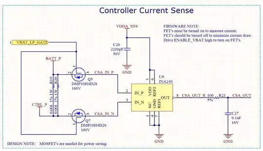
Here is one small snippet that I guess is OK to share (I am the creator of the image):

enter image description here

I don't think there is any convention. But it is definitely a good idea to put notes in the schematic. In the past FW engineers have asked me to put them in there and I try to remember to put in the kind of stuff they would want to know.

For the design notes, the goal is to spare a subsequent EE (or me 6 months later) from having to go look up a bunch of stuff in datasheets or guess at motivations.

For the FW notes the goal is to save the FW engineer time, especially if the functionality of some part of the circuit is contingent on other IO pins. If you have to drive an IO pin high to enable a sensor. I would rather just put that note in the schematic (like in the example) than have the FW engineer come to me later and say "I don't think the current sensor is working.. I have been trying to get a reading for a whole day and it is always zero" or whatever.

Likewise, if there is a sensor connected to an ADC input I want to put enough information in the schematic so that the FW engineer can write the code without pulling up the datasheet for the sensor. If the sensor is programmable or elaborate and complicated, then that would be different, I guess. But for simple sensors I would try to explain it in the schematic.

user57037
  • 28,915
  • 1
  • 28
  • 81
  • 7
    +1 I like how you grouped the notes into topics, so the relevant people are more aware of them. If I would change something, then I would probably choose a different font (color and/or style) for the notes and the components, to make the two more easily discernible. I also like to wrap boxes around notes. Essentially I make them look more like markup and less like schematic. – tobalt Mar 22 '22 at 08:27
  • @tobalt in this day and age I think you are right. When I started, we would conduct design reviews with schematics printed out on 11x17 inch (aka tabloid) paper sheets. In those days, I would always create the PDF of the schematic in black and white so it was more legible. So I didn't worry as much about colors in the schematic editor because I knew most people would be reading black and white. But nowadays nobody prints schematics. They look at them on a screen, and the colors can be very useful. – user57037 Mar 22 '22 at 21:47
  • +1 for the layout notes (esp. towards transistor level integrated circuit design). Not only does this tell the layout engineer specifics of how to layout (common centroid, guard rails, etc), but it can cover you later on. – pat Mar 22 '22 at 22:33
  • 2
    As a firmware developer, I would *love* to work with electrical engineers who put this kind of thought and care into their schematics. Not only does it make it easier for me to produce the correct code the first time (which saves *them* time, because it means I don't have to keep going back to them for help troubleshooting), but it also means that the circuit designer had to think about these things in advance, which helps *them* to avoid design errors that are costly or impossible to fix later. (I've come across so many of these.) – Cody Gray - on strike Mar 23 '22 at 00:28
  • However, you might want to leave those possessive apostrophes to grocers. :-) – Cody Gray - on strike Mar 23 '22 at 00:31
  • 5
    I do this too. I typically use different font colors for different types of notes with a legend on the first page. Design notes are blue, layout notes are green, and firmware notes are black. To avoid crowding the schematic pages you just put less on each page and have more pages. I also typically make a separate PowerPoint that goes into great detail about my design equations and decisions which becomes useful for design reviews or if someone (including me) needs to go back and see why I did something a certain way without digging. – Ryan Mar 23 '22 at 01:43
  • @CodyGray interesting. For some reason I thought it was correct to pluralize acronyms with an apostrophe followed by 's.' I will try to remember to omit it in the future but sometimes my fingers have a mind of their own. It seems that many people use the apostrophe, even though most style guides say not to use it. – user57037 Mar 23 '22 at 17:27
1

Initially when I started creating schematics I was quite reserved with my notes... now I go to town; as part of my learning process, I write notes to my future self so I can understand what's going on in a year when I come back to a schematic. I have found that when looking at a schematic after a long time of not working with it, it's easy to have no idea what's going on. Of course, there are many other techniques other than notes that help to achieve clarity for your future self; for instance, segmenting parts of the schematic into clearly defined modules (e.g. MCU, power, etc).

If I was sharing my schematic with other engineers, I'd probably calm down a little and keep it to essential information as not to overload (i.e. not spelling out what some may call obvious).

Schematic notes

Nick Bolton
  • 2,043
  • 8
  • 31
0

I've never seen a convention for this. To add my two cents, on the schematic, I'd only point to a "readme.txt" file stored in the same computer's directory as the schematic. The advantages I see: In the future, not everyone will be able to open/view your schematic files, and anyone will be able to alter or share the text file (of any growing size) if need be.

kackle123
  • 283
  • 1
  • 7
  • I've done this before. It works in a pinch, if you only have one or two notes, but it is not a great solution. The information becomes split up from context, which makes it a lot harder to digest. You effectively have to write an entire hardware design manual in that readme.txt file, which is unwieldy enough with a proper document layout system and practically impossible with a text file. – Cody Gray - on strike Mar 23 '22 at 00:31
  • @Cody Gray - If the notes are tiny, I agree, then one might risk the small chance that non-electronics people won't be able to view the schematic. If there is a lot of information, then there's no room on a schematic anyway. – kackle123 Mar 23 '22 at 19:27