0

Lets say we have a circuit as shown in the image diode circuit
Given that we know the impedance of the resistor as well as the PD of the voltage source, how can we predict the voltage drop across the diode? The characteristic V-I plot of any standard diode shows that for different voltages across the diode the current passing through it is different. So it is enough for us to obtain the voltage drop across the diode to find out the current flowing through it. However in order to obtain the voltage drop(without actually measuring with a voltmeter and only using analytical methods) we need to know the impedance of the diode which in turn depends on the voltage drop across the diode(non-linear nature of diode V-I). I would like to know how this problem is resolved.
toolic
  • 5,637
  • 5
  • 20
  • 33
  • 1
    If the diode is well polarized, just draw the "load line" and "solve" graphically. Take into account the temperature ... – Antonio51 Mar 20 '22 at 17:53
  • 2
    You could apply the Shockley diode equation [like this](https://electronics.stackexchange.com/a/592785/38098). The Lambert W-function is applied in written papers. A good example can be found in ***"Exact Analytical Solution of the Diode Ideality Factor of a pn Junction Device Using Lambert W-function Model"*** by Habibe Bayhan & A. Sertap Kavasoglu. The semiconductor research community, and those electrical engineers supporting instrumentation design for research by physicists, are well-familiar with it and use it. Most "clinical practice" engineers, on the other hand, are not and do not. – jonk Mar 20 '22 at 19:55

4 Answers4

3

The diode is reverse biased so almost no current flows through it and voltage over diode is almost identical to the supply voltage.

Actual values depend on voltage V, resistanve R and particular type and model of the diode, temperature etc.

Typically you would just draw a load line (how much voltage at diode would cause which amount of current to flow in the circuit) and then superimpose the diode I-V curves to see where they intersect.

That is good enough solution as typically there will be manufacturing tolerances etc.

Justme
  • 127,425
  • 3
  • 97
  • 261
0

I would like to know how this problem is resolved.

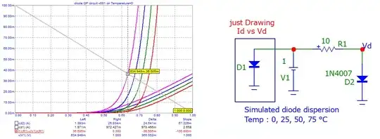
If the diode is well polarized, just draw the "load line" and "solve" graphically.

The "load line" is drawn as usual by passing between 2 points.
The first point is obtained by \$(Vmax, I=0)\$ and the second point by \$(V=0, I=Imax=Vmax/R1)\$, hence the equation of this line in the diagram \$(I, V)\$, i.e. \$I(V1) = Vmax/r(R1)-v(V1)/r(R1)\$.
r(R1) and v(V1) is the syntax for the simulator as they are "variables".

Take into account the temperature ... Diodes under test are 1N4007.

enter image description here

If diode is reversed, then this is the figure ...

enter image description here

Antonio51
  • 11,004
  • 1
  • 7
  • 20
  • Your circuit is much different from the circuit in question, so that your results are not applicable. – Elliot Alderson Mar 21 '22 at 00:08
  • This circuit is only to show HOW it can be solved. The original circuit is just a "reversing" of the diode. Current would only be more "little". – Antonio51 Mar 21 '22 at 07:49
  • > I would like to know how this problem is resolved. NB: The voltage of the OP question was not "precised" (positive or negative). – Antonio51 Mar 21 '22 at 08:09
  • Perhaps you should add some text **explaining** your answer. How is the OP supposed to infer your meaning from a screenshot or a wall of equations? – Elliot Alderson Mar 21 '22 at 10:39
0

If you have a model of the diode you can solve the equation numerically, or analytically if you make some minor simplifications.

If all you have is a V-I curve, you solve it graphically with a load line, as suggested. Or simply iterate a couple times as would in solving an equation numerically. For example, you assume 0.7V drop, calculate the current, then look at the forward voltage resulting from that current and correct. It will typically converge very quickly, especially if V >> Vf.

Since your diode is reverse biased, the current will be less than the maximum leakage current (a strong function of temperature, by the way) shown in the datasheet. If the resistor drops much voltage at the typical leakage current, the reverse voltage will be very unpredictable and temperature-dependent.

Spehro Pefhany
  • 376,485
  • 21
  • 320
  • 842
0

As @Justme pointed out, your diode is reverse biased, so none of this applies, but I'll answer as if it were forward biased.

Load lines, as explained in a number of answers, are very useful here -- even if you have only the approximate I/V curve of the diode.

For me, the real answer is that a good design will not depend upon the exact diode drop, so we never really bother figuring it out.

Families of diodes, and different color LED's, will all have about the same voltage drop. We look it up, use it to robustly design such that the approximate number is good enough, and then we move on. It's not a robust enough parameter to design around. It's sort of like the \$\beta\$ of a transistor -- if your design will only work for a very tight value of \$\beta\$, the design isn't robust enough to be reliable. Similar issues here.

The load line should convince you that once you have the ballpark resistor correct, then slight changes in it's value will change the current across the diode only slightly.

If you need better than that, you buy a diode who's data sheet you have access to, pull out the minimum and maximum voltage drops, and design to those -- but those cases should be fairly rare. In fact, these cases are so rare that many data sheets will only give you a value of \$V_f\$ for a given forward current.

Scott Seidman
  • 29,274
  • 4
  • 44
  • 109