check assumptions with Ohm's Law
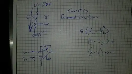
All Op Amps must match Vin+=Vin- within their Vcm common-mode acceptable range in order to work in the linear range on the output.
Since R2 determines that input difference. R2= U1/I2 = 1k.
Your supply voltages and output linear range determines the limits on I2 and R1,R2.
Since 10 mA * 10 k = 100V, that would not seem appropriate so it will saturate the output and never reach 10mA. But something < 1V drop or <100 ohms might be your expected load.
But I suspect this restricts your range of loads too much.
So a better idea is to attenuate your 10V input range to the maximum drop you want to sacrifice in reducing our output voltage range for a 10 mA load.
Consider 100 mV drop for R2 @ 10mA then R2 is 10 Ohms and now V1 must be attenuated from 10V to 100 mV going into Vin+. That works better. But now you need an Op Amp with PNP differential inputs or Pch inputs to sense neat 0V for a single supply.
Then your load R1 can be anything from 0 ohms to 1k = 10V for a 12V supply with V1=10V.
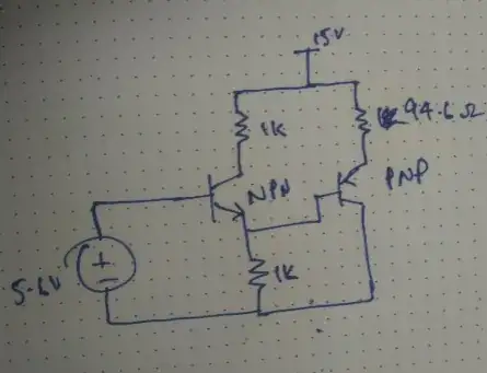
simulate this circuit – Schematic created using CircuitLab
Don't worry about error tolerances for now and just accept up to 3% error with 1% parts using R3=9.9k. or if 10K add an extra 1% error as R2,R3,R4 all contribute to the transfer function equally for sensitivity using the partial derivatives.
Since the input attenuation range is 1:100 the conversion or transfer function is Io=V1/10.
Io/V1= (R4/R2(R3+R4)) = k = 1/1000 A/V = 1 mA/V
tolerances
To compute tolerance sensitivity, one takes the partial derivative of the transfer function , in this case (=k) w.r.t. each component and make assumptions where necessary.
also consider input offset error if input is reduced to 0 to 100mV then if Vio= 2 mV max that is 2% offset error and you have to change something the R ratio or the Op Amp Vio.
e.g. dk/d(R2)=