0

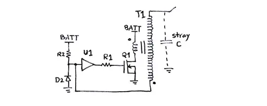
I have the circuit in the image below working with the PT4115 driver. I use it to light a 10W LED from a 24V DC source. The LED draws close to 1A. I can control it with a 5V PWM signal from an MCU.

Original circuit

I'd like to add a second 10W LED, in different color, and I'd like to be able to choose which one is going to "light up" using another output pin on the MCU. If the pin is low, it would light LED one, if it's high, it would light LED two, never both at the same time.

Can anyone help with an "equivalent switch" simple circuit to be able to perform like this, like in the diagram below?
wanted circuit

JRE
  • 67,678
  • 8
  • 104
  • 179
Rodrigo
  • 467
  • 2
  • 8

1 Answers1

0

You could use two high-side P MOSFETs switch circuits, inserted between 24V and the anode of each LED. The basic idea of the circuit can be seen below. The PMOSFET Q2 is turned on by pulling the gate typically 5-12V (gate threshold voltage) below the source voltage, i.e. 24V. This is what happens when Q1 is turned on. enter image description here

In your case, the LED will be in place of R3. You need one of these circuits for each LED. To ensure the Vgs max of the power MOSFET Q2 is not violated, you will probably need increase R2 to 2x10k and wire the gate of Q2 to the midpoint of these resistors.

mr_js
  • 1,053
  • 6
  • 13
  • Hi! I got the idea, but I have some doubts. First is that the leds are not connected to GND. They are connected to LED-, which are connected to an internal mosfet in the driver. So I couldn´t connect each in the place of R3. Also, – Rodrigo Mar 13 '22 at 11:12
  • When the internal mosfet is on, it should be internally connected to ground. In any case the PMOS will be biased on, which allows current flow through the correct LED. – mr_js Mar 13 '22 at 11:19
  • Ok.. but how would I wire the two circuits to act differently using only one input (low for LED1 and high for Led2)? – Rodrigo Mar 13 '22 at 11:20
  • A simple way would be to use an NPN inverter circuit to drive Q1 in one of the circuits. Take a look at this answer: https://electronics.stackexchange.com/questions/30238/how-to-invert-a-digital-signal – mr_js Mar 13 '22 at 11:30
  • HI! ok, done it.. virtually! When MCU signal is 0V one led lights. When it's 5V, the other lights, never both at the same time. Can you check if this is right? Also if the values of the resistors for the transistor make sense? I made the simulation in the online sim falstad: https://tinyurl.com/y9vyholf – Rodrigo Mar 13 '22 at 14:52
  • You may also need a resistive voltage divider after the NPN inverter in case the MOSFET gate can't handle 24V. This will reduce the gate voltage. As long as you are not switching back and forth between LEDs at a rate of kHz you will be fine. Otherwise the MOSFET controlled by the NPN inverter may heat up. – mr_js Mar 13 '22 at 19:15
  • Ok, done! And added the internal driver´s N-Mosfet to the circuit. Here it is: https://tinyurl.com/yd229un7 .The Leds will be maybe changed from one to the other once an hour. This driver uses PWM to control the Led brightness. Would there be a problem if the PWM is so close to fade the led completely, almost turning it off, that the circuit could malfunction, not having enough voltage for the mosfets or transistor to work properly? – Rodrigo Mar 13 '22 at 23:03
  • I don't think so because the correct PFET will definitely be biased on and thus act as a short circuit. The only way you can be completely sure is to build it and test it for all boundary conditions. – mr_js Mar 14 '22 at 10:34
  • Hi! Finally I built a test circuit and it seems to be working perfectly. Thanks so much! I have one more doubt: I'm using small SMD FETS (A03401 for the P mosfet (http://www.aosmd.com/pdfs/datasheet/AO3401.pdf) in my circuit. In the datasheet it says the continuous drain current is MAX 4A. I'm using max 1A in my circuit. Would it need some kind of heatsink or at this current I'm using it will remain cool? In my test circuit it remains cool after some minutes of testing, by I'd like to be sure.... – Rodrigo Mar 30 '22 at 14:45
  • Great to hear. The PFET should be fine if you are only driving it at 1A. You could calculate the conduction losses at 1A and compare it to the worst case power the device can dissipate. But this will be fine. P.S. If this solved your problem, don't forget to accept the answer. – mr_js Mar 31 '22 at 14:30