15

I am under the belief that North American residential power is a special case of two phase power adequately described by the term split phase. Clearly I am in the minority and want to be convinced otherwise but have not found any convincing explanation.

I always assumed there was a functionally or historical reason but I'm always met with an inadequate theoretical explanation. Best I can figure it's a contextual reason to help the people who work on motors or it's to differentiate from systems with two phases that are 90deg out of sync. A theoretical explanation seems to require a unique definition of phasors or to define our electrical system by the loads we attach rather than the voltage source supplying the current with a zero point reference.

Here is my theoretical argument. Pretty simple. Transformers transform. With the secondary having a center tap, 3 wires, each pair of wires has either a unique phase angle from the other pairs or a unique magnitude, even accounting for direction. Now arbitrarily calling the center tap 0v. The other two legs are 180deg out of phase. (Note, grounding an edge would give the same phase angle but different magnitudes, still a two-phase system.)

chicks
  • 183
  • 3
  • 8
9Harris
  • 159
  • 1
  • 8
  • Comments are not for extended discussion; this conversation has been [moved to chat](https://chat.stackexchange.com/rooms/134743/discussion-on-question-by-9harris-why-is-north-american-residential-power-called). – Voltage Spike Mar 13 '22 at 20:46
  • @mkeith You said that eg a clothes dryer needs a neutral AND 240V. That means that IF this 240V is centre tapped you could get one 120-N feed but the other 120V feed would be 240-120 and 120 above ground at its lowest voltage, so could not be sensibly usable as a 120V feed. Yes? || I imagine (and may be wrong) that a 240V feed with N at one end and not at the centre tap doe not allow 120V feeds. || A;; this is just implementation specific and does not really relate to the original question as to whether two 120V windings at 0 degrees should be considered to be two separate phases. – Russell McMahon Mar 14 '22 at 01:09

11 Answers11

31

Because it is a single phase, with a center tap.

That's all it is. There's nothing more exciting than that. It is a 240V transformer secondary with 3 taps at 120V spacing.

Most installations have a safety earthing system (not to be confused with electronics GND/Vss). Leakage in the transformer might float all 3 taps thousands of volts above earth. We don't want that, so we pick 1 tap and bond it to the safety earthing. Does that make sense?

The one we bond to earth, we call "neutral".

Let's imagine they picked the tap at the end of the transformer winding. Neutral would be at the "bottom" and there would be a 120V tap and a 240V tap. * In that case, you would unquestionably call it single-phase with taps - right?

Using the center tap for neutral is marginally less dangerous, since it means neither hot wire will be more than 120V to ground. The transformer is exactly the same. Nothing has changed but the bonding.

You can call it 2-phase if you really want to; I see where you're not wrong, in a principled sort of way. But the whole point of language is to communicate with others. And others think 2-phase is a 4-wire system with two loops 90 degrees out of phase.


* Once I found a 120V service like this, a fault had caused "the white wire formerly known as neutral" to be 120V from ground. Some circuits had a 0V hot, others had a 240V hot. Everything worked fine. Nothing cared. It was found during routine maintenance.

  • 17
    "Nothing cared" because, by the grace of the flying spaghetti monster, there wasn't a further fault that exposed the hot neutral and killed somebody. – Reinderien Mar 13 '22 at 14:12
  • 1
    He means none of the devices cared. – Drew Mar 13 '22 at 22:16
  • 1
    That's why you shouldn't touch either wire unless you have checked they are dead. – Rich Mar 14 '22 at 00:11
  • 2
    @Reinderien: The safe wire is supposed to be Ground, not Neutral. – MSalters Mar 14 '22 at 16:45
  • 1
    The system with voltages 90 degrees out of phase that you mentioned might best be called "four phase". Re-read Reinderian's comment above. And remind me to wear rubber gloves if I ever visit your house. – richard1941 Mar 18 '22 at 03:19
22

Why is North American residential power called single phase?

Because that's exactly what it is.

Utility power in North America is distributed via single-phase transformers with their primaries being fed 12.47 kV using 2 lines of a three-phase system or 7.2 kV using a line and neutral.

The distribution transformers, which are pole-mounted, are also known as a 'pole pigs'.

enter image description here

The single secondary winding L1 - L2, with an earthed centre tap designated as the neutral, provides a single-phase 240 V supply between L1 and L2 and two single-phase 120V supplies, which are out-of phase by 180°, between L1 & N and L2 & N.

Hence it is referred to as a 'single-phase, three-wire' system or 'split-phase' system.

I am under the belief that North American residential power is a special case of two phase power adequately described by the term split phase.

A theoretical explanation seems to require a unique definition of phasors or to define our electrical system by the loads we attach rather than the voltage source supplying the current with a zero point reference.

A single-phase alternator, has a single winding that produces a single, continuously alternating voltage.

A two-phase alternator, now obsolete, had two windings spaced 90° (electrical degrees) apart with the voltages generated in them having 90° phase displacement.

A three-phase alternator, has three windings spaced 120° apart with the voltages generated in them having 120° phase displacement.

A single phase induction motor, having two windings spaced 90° (electrical degrees) apart is actually a two phase motor. The single phase supply is split into two phases that are out of phase by 90°, by connecting a capacitor in series with one winding. A single phase induction motor is hence referred to as a split-phase motor.

The 'single-phase, three-wire' system or 'split-phase' system, with its two voltages being out of phase by 180°, does not qualify as a two-phase system.

vu2nan
  • 15,929
  • 1
  • 14
  • 42
  • 1
    Why doesn't your diagram show a neutral connection on the left side? – Reinderien Mar 13 '22 at 13:59
  • 2
    @Reinderien - Hi, The neutral connection is not shown on the primary side since it would be connected only for a 7.2 kV primary and not for a 12.47 kV one. My answer has been edited further to your second comment. Many thanks. – vu2nan Mar 13 '22 at 15:34
  • If L1-N and N-L2 are out of phase by 180deg how is it a single-phase? – 9Harris Mar 13 '22 at 20:34
  • 2
    @9Harris L1-N and N-L2 are in phase. L1-N and L2-N are out of phase by 180 deg. – user57037 Mar 13 '22 at 21:44
  • @Reinderien: A nice feature of not having a neutral connection (delta connection) is that third harmonics are blocked. – richard1941 Mar 18 '22 at 03:24
17

The "single-phase" terminology is nearly always used in the context of three-phase supplies as this is the standard method of power transmission used throughout the industrialised world.

enter image description here

Image source: Plug Socket Museum.

When you study the diagram of the delta-connected high-leg transformer arrangement it becomes clear that the L1 - N - L3 output is derived from one phase of the three-phase supply. There is no phase rotational direction associated with them so, on their own, they cannot drive an induction motor without additional help to start them in a particular direction.

I think calling it a two-phase system is likely to imply a phase angle other than 180° and lead to some confusion. "Split single-phase" would give the least risk of confusion.

Transistor
  • 168,990
  • 12
  • 186
  • 385
  • 2
    L1 and L3 have a phase rotation of 180deg. I understand this would not work to start an induction motor but it still is not a single-phase. Though I see how it would potentially confuse a person who works on motors – 9Harris Mar 12 '22 at 18:40
  • 1
    Using one single phase only and a transformer with two secondary windings you can get 180 ° phase shift by reversing polarity of one secondary winding. – Uwe Mar 12 '22 at 21:33
  • @9Harris L1 and L3 have a phase rotation of 180deg. when N is used as reference. But to L2 the phase rotation of L1 as well as L3 is 120deg. – Uwe Aug 03 '23 at 09:21
9

This is perhaps opinion based, but I believe the reason we avoid the term "two-phase" is historical. A long time ago, two phase power with a 90 degree phase angle was somewhat commonly used. The term "split phase" differentiates our domestic electrical system from two-phase 90 degree power.

I am not sure if this is relevant to your question or not, but the power on the utility poles in North America (as well as buried distribution wires) is truly single phase in many places. Split phase power is created by the center tap on the transformer secondary as you say in your question. So when people refer to North American power distribution, in many places, that power is correctly called single phase. The actual power inside the residence and at the service entrance could be called two phase or split phase. So in some specific instances, it may be perfectly accurate to say "single phase."

Also, just for completeness, in many places in north america, power distribution is three phase. For example at my house, the power on the utility poles is three phase power. The transformer that supplies my house converts one of those phases to split phase residential power. But a second transformer on my property supplies a second meter with three-phase power from all three phases of the utility wires. That second meter is for a well pump. The reason for that is definitely off-topic. But basically there is a three-phase powered well pump connected to that meter, and the electricity used by that pump has to be paid for separately from my utility bill.

user57037
  • 28,915
  • 1
  • 28
  • 81
  • _Split phase power is created by the center tap on the transformer secondary_ I strongly disagree. `Split phase` is just a non-technical term used instead of a physically/electrically correct one, eg. `center taped single-phase`. -- _actual power inside residence & at service entrance could be called two phase_ No! In an AC `n-phase` system with `n>1` the **different** phases need to be **out of phase** to each other, otherwise they wouldn't be different phases. – Limer Mar 13 '22 at 14:38
  • The question is primarily why the **term** "_split phase_" 'descibes' a single phase and not a two phase system. The reason why it is a single phases system is technical and exactly the reason why **it can not be considered a two phase system** and there is **no phase shift of 180° between a split-phase L1 and L2**. They're exactly in phase, otherwise you wouldn't get 240Vrms but less between L1 & L2 (180° out of phase and it would be 0V). -- Please read my answer https://electronics.stackexchange.com/a/611853/207587 – Limer Mar 13 '22 at 17:14
  • Well okay, if you think of L1 as +120V AC and L2 as -120V AC (which makes no sense because it's **AC**) then they'd need to be 180° out of phase to get 240V -> `sin(x) - sin(x+pi) = 2* sin(x)`. But that is a kinda wrong way too look at it because as stated in my answer **one core can only transform one phase**. Measuring from GND to L1/L2 kinda leads to that view but look at it like that: `(GND+L1) + (GND-L2)` and suddenly they are in phase. Eg. you need to measure from L2 to GND and from GND to L1 and they are in phase. – Limer Mar 13 '22 at 17:36
  • now you're kinda contradicting yourself. If one sees both L1 and L2 just as hot wires **and** 180° out of phase then V between L1 and L2 would be 0 because the out of phase waves would just cancel each other out. If, on the other hand, one measures the potential difference on one single scale between L1 and GND & L2 and GND with (GND at 0V) you'd have +120V and -120V (or vice versa). Now those two Ls are the inverse of each other `*-1` (==180° out of _phase_) because `sin(x)-sin(x+pi) = 2sin(x) = sin(x) + sin(x)` – Limer Mar 13 '22 at 18:09
  • Well, if there is only one phase, why not just connect 'em and see what happens? – richard1941 Mar 18 '22 at 03:29
  • @richard1941 if you are replying to Limer you may want to insert a tag: (at) Limer. EESE doesn't automatically notify people in the comment section just because they also made comments. It did automatically notify me because you posted a comment under my answer. – user57037 Mar 18 '22 at 03:54
4

The nomenclature is largely historical, and indeed there was (briefly) a 2 phase 90 degree system used as this could run an induction motor (Which 180 degree two phase power cannot without help).

Of course two phase (of either variety) takes the same number of conductors as three phase delta which produces way less torque ripple and is generally superior, so it took over rather rapidly.

You could call 120-0-120 two phase, but you will just confuse folk, which is a good enough reason not to.

Dan Mills
  • 17,266
  • 1
  • 20
  • 38
  • 1
    Just to be clear, it's because at one point in time we reserved the term two-phase for the 90deg system? (or for the most part. I get things can have multiple reasons.) But are you also implying that it would make theoretical sense to call it a single phase system as well? If so, I would like to know how. – 9Harris Mar 12 '22 at 17:24
  • 2
    It all comes down to definitions, and I suppose a reasonable definition of a polyphase system is one in which you can combine the phases to produce arbitrary phasors in 2 space, which is true of a 90 degree two phase system (clearly), is true of three phase, but is NOT true of split phase. In other words a 90 degree two phase or 120 degree three phase system can produce a rotating field, a split phase system cannot. – Dan Mills Mar 14 '22 at 15:30
  • The first computer I worked on made extensive use of 90 degree separated sinusoids to sense the angle of a shaft. The phase in the rotating secondary was the actual shaft angle. It flew an F-101 interceptor aircraft (when it was working correctly). – richard1941 Mar 18 '22 at 03:36
  • @richard1941 Syncro resolver? Also very common in WW2 gunlaying systems (Which were really electro mechanical computers running REALLY BIG servo drives), fascinating technology. – Dan Mills Mar 18 '22 at 11:44
3

The two split phases do not meet any of the usual constraints usually implied by the term "separate phases"

In a true N phase system the voltages in each isolated phase are at 360/N degrees electrically. In the North American system there are 3 such phases, each 220 V and each at 360/3 = 120 degrees to the other.

It is customary to split each of these phases into 2 x 110V non-isolated portions. Each of these is constrained to be at the same electrical rotation by virtue and constraint) of being on the same core of a 3 phase transformer and are unable to be isolated electrically without the provision of an additional isolating transformer.

It would be possible to physically split the winding at the centre point and to provide two voltages, each still in 0 degrees or 180 degrees isolation to each other - but this is not done. Doing this would require that each of the 100V windings be connected to Neutral at one end, and they would then be unable to be connected together to allow the full 220V phase to be used in eg heating applications.

Russell McMahon
  • 147,325
  • 18
  • 210
  • 386
  • So each of the splits is actually originating form a single phase of a three-phase distribution transformer somewhere? – DKNguyen Mar 12 '22 at 16:06
  • 2
    @DKNguyen Yes - each 220V phase winding is centre tapped. NB: I'm in NZ - I think I'm right - but sometimes I'm wrong - but I think I'm right :-) – Russell McMahon Mar 12 '22 at 16:09
  • 1
    Your "true N phase system" seem to me as a special case again. Seems like your describing a symmetrical multi phase systemm – 9Harris Mar 12 '22 at 16:17
  • 4
    To me, if each 110v sections were isolated then it would be two single-phase systems. I find a conversation on how split-phase power is commonly created seems to have little baring on the question though I'm willing to be convinced otherwise. It seems your answer is a functional one - being such, can you elaborate on the "usual constraints" and "usually implied"? The only electrical system I have heard people refer to as two phase is when the two phases have a 90deg relative rotation which seems to not fit into what you call "usually implied" - i.e. a symmetric multiphase system. – 9Harris Mar 12 '22 at 17:01
  • @9Harris There are blurred boundaries :-). Imagine a 3 phase system with 120 degree rotation in time between the 3 phases - name the phases RGB. If we how have two windings on the R phase that are electrically isolated but may be arranged at 0 or 180 degrees we could call them eg Ra and Rb. Similary we could have Ga Gb Ba Bb. If we join together any two "subphases" with the same primary letter eg R we get double the voltage (or no voltage). If we mix any subphases with different primary letters eg Ra Gb we get voltage adding as the vector sum. I know this is obvious to you - – Russell McMahon Mar 13 '22 at 07:00
  • ... and it is a fundamental difference in how the subphases can be utilised and combined. || I have seen two phase systems where the two phases are 90 degrees offset. This has no apparent advantage. The sum (or difference) of the phases is a sinusoid greater ij amplitude than either of the components but not double. The same output waveform could be obtained from a single phase with double the single phase voltage for the same wire. || 2 phase systems offset by other than 90 degrees may have some purpose, but I've not seen them used. – Russell McMahon Mar 13 '22 at 07:22
  • Many North American dry-type mains transformers (LV-LV) *do* have split secondaries, and *can* be wired to generate two independent and isolated sources of power – ThreePhaseEel Mar 13 '22 at 07:22
  • @ThreePhaseEel I argue above that these are still subphases of the same main phase. ie if added the voltage doubles. This is not true of any "normal phase voltages" in a 3 phases system. It begins to become a matter of nomenclature. – Russell McMahon Mar 13 '22 at 07:26
  • Hopefully I'm not seen as trying to be pedantic or difficult here. (It happens :-) ). My perspectives are genuine ones. In NZ we have 3 x 230V phases and never centre tap them to 115V feeds. – Russell McMahon Mar 14 '22 at 01:10
2

The answer about the pole top transformer is correct as far as it goes, but the primary of the pole top transformer (usually in the 11000-33000 volts) is really one leg or a high voltage 3 phase coming from the local distribution substation. If primary of the pole top transformer has one high voltage line and a ground (which which is connecting to an earthing ground at the base of the pole, then it came from a 3-phase "Y" distribution from the substation (if the transformer primary has two HOT wires, then from a 3-phase delta) transformer. That, in turn was driven by a primary transmission line of 69,000 to 200,000 volts.). Thus, what runs down the street is ONE (single) Phase of a three phase power system. Thus, refered to as a SINGLE PHASE final distrubution.

Just follow the single phase back toward the substation, and you will eventually come to a pole which has all three phases (feeding different neighborhoods or industrial complexes)

The local/area substation transformer primary voltage is usually anywhere between 69,000 volts and 240,000 volts which were probably an intermediate voltage stepped down from the long distance transmission lines ("the Grid") which could be up to 2 million volts. Next time you drive under one, count the wires...3 HOT lines for each phase.

Dan, BSEE, 40 years experience, starting as Asst. Operator of a power station for BVG&E

Dan
  • 21
  • 1
0

Because it just is single phase

frequency diagram Octave code:

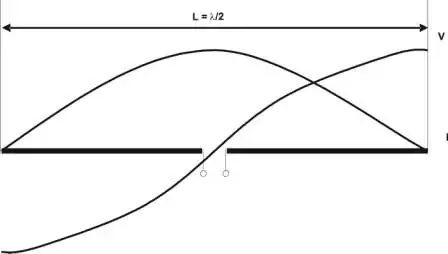
x = 0:0.1:(2*pi+0.5);
plot (x, (x-x), "-k;reference/neutral;", x, sin(x), "-r;Line1 [=sin(x)];", x, 2*sin(x), "-m;Line2 [=2*sin(x)];", x+pi, sin(x), ":^g;Line1+180deg;", x, -sin(x), "--vb;Line1*(-1) [=-sin(x)];")

#1 - ground at one outer tap

  • Black reference/neutral is the grounded outer tap (=GND henceforth in this post).
  • Red Line1 is the middle tap with 120Vrms to GND.
  • and Magenta Line2 the other outer one with 240Vrms to GND.

Voltage between Line1 and Line2 is 120Vrms too. -> 120V+120V=240V -> these two "120Vs" must be in phase and not 180° out of phase or you wouldn't get 240V.

As shown/stated by @vu2nan the pole transformer has just one primary/input winding and only one core and one output winding (with a center tap). Even if different phases were to arrive at the primary winding (which is electrically impossible) the winding itself would only swing with the sum of those phases (replace phases with frequencies in this sentence and it makes sense...).
Thus everything on the secondary winding must be in one phase too (there may be an exception if the transformer isn't magnetically/mechanically balanced mirror-able).

#2 - GND at center tap eg. "split phase"

  • Black is the GNDed center tap.
  • Red Line1 is the 1st outer tap L1 with 120Vrms to GND.

And you have two options for the 2nd outer tap L2:

  1. it has exactly the same voltage profile as L1 / Red Line1 when you measure from GND to L1 and from L2 to GND. (use a scope where inputs 1+2 have completely isolated inputs including there grounds or two separated scopes with synced triggers(?). Basically if you measure exactly as in #1 but with a shifted GND.)
  2. or it's Blue/Line1*(-1), the inverse of L1 when you measure from GND to L1 and from GND to L2 (eg. flipped #1).

This doesn't change anything with the phase. It's still just one phase and not out of phase by 180° (or any other degree).

To mathematically get 240Vrms here between L1 and L2 you have two options again (with 1 on the y-axis being equivalent to sqrt(2) * 120V):

  1. sin(x) + sin(x) = 2*sin(x)
  2. sin(x) - sin(x+pi) = sin(x) - -sin(x) = 2*sin(x)

but sin(x) + sin(x+pi) = sin(x) - sin(x) = 0 (one 180° out of phase to the other)

Now if you want to add two times 120V together they need to be in phase. If their phases are pi-shifted you need to subtract(!) both potentials from each other to get 240V.
Mathematically the result is the same but one is is a bit more counter intuitive (from this perspective).

Why the term "phase" is out of place (here in my opinion)

Short: If you first learn this split phase out of phase you need to re-learn it when you want to work in electrical power distribution and so on (in the US you have multi-phase AC there too?).

Much longer....

Phase is usually only used with n-phase systems (with n>1) in relation to the generators.
Imagine a simplified/idealized generator with just three stator coils in star configuration 120° apart from each other and one bar-magnet as the rotor. Now if you start to turn this generator with 60rpm = 1Hz there is a 'real' phase difference between the three outputs when you compare the sinus waves between any two random but different pairs of measuring points (L1/2/3). The V-peaks on each pair follow each other 1/3 *s apart (or 120°).

Example: L1~L2 has it's V-peak 1/3s before L2~L3 but 1/3s after L1~L3. I used "~" instead of "-" here because the polarity is irrelevant for the phase. If you measure one pair in the opposite direction to the other one it's up to you to use the inverse or you'll falsely think the rotating field suddenly switched direction which can quickly lead to catastrophes (as if a big gas turbine would suddenly switch directions).
In other words: You need to decide on one rotation direction and measure along the Ls that way top get a correct result. If you switch directions in the same set of measurements the result cant be trusted.

When you you have only one phase you have no rotating field at all and cant have any 'true' out of phase "phases"...

2nd example: If you connect a new power plant to the grid and the generator is not exactly in phase with the grid it will either be sped up or slowed down by the grid to get it in phase (the grid will do the opposite but it's rotational momentum is far greater so this effect is negligible). If it's too far out of phase (eg. by 180°) it will probably destroy itself, some transformers, the turbine and more...
This out of phase doesn't really relate to the split phase system's out of phase.

Another example: modern eg. DUSPOL voltage testers and equivalent can measure the rotation direction of/between just two phases of a three phase system by - I'm not actually sure how - maybe measuring the time between V-peaks (or with a capacitively connected third pole through the handlers hands - need to test that)?
The problem with that is: Under ideal conditions you get a perfect sinus wave between two phases regardless of variations in phase difference or if it's L1~L2, L2~L3 or L3~L1. Reason is that the sum of any two sine waves with the same frequency (eg. 60Hz) and any phase shift of f<>pi is another sine wave, just with a different amplitude. (If f=pi=180° the sum is 0)
But If one measures between GND and any of the three phases the voltage tester randomly flips between right and left rotation. It would be the same in a single phase center taped system - no or randomly flipping rotation direction but between any pair of measurement points (not just between GND and L* but between Lx and Ly too).

The phase offset I know of is in direct relation to the mechanical construction of a multi-phase generator (degree between sets of coils and if two sets are 180° apart they are connected so they are in the same set...).

Why Wikipedia says "Two 120 V AC lines are supplied to the premises which are out of phase by 180 degrees with each other (when both measured with respect to the neutral)" is beyond me. As if split phase alone wouldn't be the source of enough confusion, let's throw in an out of phase.

Much better would be (imho): Two 120V AC to ground lines are supplied to the premises with 240V between the two
And maybe add (which means with respect to the grounded center tap both AC lines are inverted relative to each other)
but leave phase out if it...

RE your kinda vague questions

The common North American residential power is not a 2-phase system by any reasonably accurate technical definition. Why the confusing term split phase is used instead of eg. center tapped single phase - which would be exact, accurate and technically correct - I don't know.

The reason is purely technical but kinda depends on how you define phase in this regard. As the mathematical/physical time offset of different sine waves of the same frequency with and/or ;-) without regards to polarity.
For time offset take look at the green wave from the graph.

Calling them out of phase is very misleading imho. Maybe phase shifted? Don't like that much more so maybe phase inverted?!

Limer
  • 239
  • 1
  • 5
  • I just thought of using the edge as grounded instead of the center as an interesting example on why we don't care about the sign of the phase angle last night. I think a 0v reference independent definition is needed for Phase. Thus making L1-L2 is the same as L2-L1. – 9Harris Mar 13 '22 at 16:52
  • @9Harris - In a single phase system you indeed do not need to care about any phase angles because there's just on phase (usually). And which tap is grounded is irrelevant in that regard too. It being in the center just lowers the maximum to-ground-fault voltage from 240Vrms to 120Vrms. -- You need a common reference (0V) to define any phase. In Europe's three-phase system you still just have a normal sinusoidal 50Hz voltage between eg. L2 and L3 because the sum between the two 120° shifted phases is in itself just another normal 50Hz sine (with ~400Vrms instead of 230). – Limer Mar 13 '22 at 17:01
  • I don't think 0v reference is needed to define Phases. I actually think Phases are defined specifically without a 0v reference. – 9Harris Mar 13 '22 at 17:04
  • @9Harris - You cant even measure the Voltage with only one wire. You always need a reference. Would would you describe a phase against if you don't have a reference? Attach just one lead of your multimeter to a battery and you wont measure anything useful. Connect just one lead to a running AC motor and it wouldn't show anything useful either. Especially not any phase or frequency information. – Limer Mar 13 '22 at 17:22
  • @mkeith - `L1 & L2 are 180 degrees out of phase regardless of whether there is 0V ` L1 and L2 are the two end taps of the pole transformer and they don't 'have any phase at all'. The potential between the two is 240Vrms with a sinus frequency of 60Hz. Talking about different 'phases' when there's only one makes no sense. Wikipedia: `Two 120 V AC lines are supplied to the premises which are out of phase by 180 degrees **with each other (when both measured with respect to the neutral)**` == ... which **are in phase but measure inverted to each other with respect to neutral** (inverted = `*-1`) – Limer Mar 13 '22 at 17:54
  • Not only do you need a reference to take voltages. I believe in AC Phasor representation this make the difference between the idea of L1-L2 and idea of L2-L1 in consequential and thus not used in Phasor representation. So L1-L2 and L2-L1 care considered the in same phase. Since Phasors represent Sine waves about 0, no dc offset, anything in the same phase would add. I DON'T think one can construct a 3 wire system where two voltage Phasors would subtract, which would be the case if we included 180 deg Phases – 9Harris Mar 13 '22 at 18:47
  • @mkeith - Why specifically? Thou I have stumbled over a, lets call it, _handicap_ in my thinking. I will update my answer and explain why it's fundamentally flawed to describe L1 and L2 in a single phase system (even on a split phase transformer) to be 180° out of phase. - - - - @9Harris I'm not a 100% sure but yes (i think). L1-L2 and L2-L1 are just the negative/inverse of each other because the _polarity_ is switched when measured with a scope. RE "no pi flipped phases + 3-wire sys." - It kina depends how you measure... `sin(x)+sin(x) = sin(x)-sin(x+pi) = 2*sin(x)` and `sin(x+pi) = -sin(x)` – Limer Mar 13 '22 at 19:18
  • Exactly, it depends how you measure. When the low tap is defined as neutral, you have two inphase outputs, one the positive cycle the middle tap goes to positive peak of 120VAC and top tap goes to positive peak of 240VAC. But it also means that the bottom tap has 120VAC negative peak compared to middle tap, and still top tap has 120VAC positive peak compared to middle tap. Thus does not break the logic of relative voltages, and proves top and bottom taps are 180 degrees apart, as you must subtract sin(x) from all taps if you change neutral/reference from bottom tap to middle tap. – Justme Mar 13 '22 at 19:31
  • @Justme - What happens when the power grid is down and the first generator starts again? **Are the first `sqrt(2)*120V` peaks on L1 & L2 measured against GND 180° out of phase? Of course not.** they are exactly in phase. Because the the pole transformer has only one winding which can only react to one set of equivalent corresponding windings in the generator(s) and the whole output winding reacts as one too. The peaks are identical or inverted depending how you measure (L1 to GND & GND to L2 **VS** L1 to GND & L2 to GND). `-sin(x) = sin(x+pi) = cos(x)`. Calling that **out** of phase is flawed. – Limer Mar 13 '22 at 20:13
  • 1
    @Limer one phase comes in to your house transformer. One 240VAC phase comes out. But, it is split into two 120VAC phases because the center tap is defined to be 0V. When voltage starts going to positive direction, top tap goes positive in comparison to center tap and bottom tap, right? Which means center tap goes positive compared to bottom tap, right? So it means bottom tap goes negative in reference to center tap, and center tap is artificially defined as the 0V point always, so top goes positive, bottom goes negative. Transformer splits the phase into two lives of opposite phase. – Justme Mar 13 '22 at 20:53
0

To my knowledge, North American residential power uses three systems.

120/240 single phase is straightforward, one transformer winding with the centre tap connected to a grounded conductor. The two live conductors have phase angles of 0 and 180° with respect to the grounded conductor.

120/208 wye is also straghtforward. 3 windings are each connected between the grounded conductor and a 'live' conductor. The three live conductors are 120v and 120° in phase apart with respect to the grounded conductor, and 208v between any two live conductors. Residential properties typically use two live conductors and the grounded conductor, with high powered appliances connected between the two live conductors to take advantage of the 208 volts.

120/208/240 delta however is an oddball system. They use 3 transformer windings in a 240v 3 wire delta connection, but connect the centre tap of one winding to the grounded conductor. This creates two live conductors at 120 volts to the grounded conductor, and 0° and 180° phase angles, and a third "high leg" conductor at 208v and 90° phase angle.

Single phase resedential connection on that system bring in the two '120v' live conductors and the grounded conductor. It is not possible to use the voltage difference between these three conductors to create a rotating magnetic field. They are electrically equivalent to the "split-phase" system, and so are called "single phase".

Liam
  • 311
  • 1
  • 4
-1

Calling it Single-Phase has a technical reason/definition though there are Functional reasons as well. Calling it Split-Phase leaves little ambiguity.

Misconceptions in the question: Phasor and Phase are not the same thing. Phases do not have magnitudes, Phasors do. More to come later. The person asking the question seems to be not satisfied by unless presented by a technical definition for a Phase which is best left for a mathematician.

Functional Reasons: See other answers for motors (and other loads), 90deg systems, and how Single-Phase is commonly made.

Technical Answer: This is probably best left to be answered by mathematicians but here is part of the story. As I said above, when we say Phase we leave out magnitude. We also do not care about the sign of the direction! Since signs are ignored using the 0v reference as a naming point becomes pretty meaningless and of course it also makes 180deg the same as 0deg. So an AC voltage wave from point1 to point2 is considered the same phase as from point2 to point1. (As pointed out by @Limer). For nomenclature it can be handy to call N-L1 and N-L2 "Sub-Phases" in Split-Phase system. (As mentioned by @Russell McMahon).

As pertained to Split-Phase: The 3 wires give 3 Phasors: L1-N, N-L2, L2-L1. But since Phases are non zero point reference dependent N-L1 and N-L2 are not considered 180deg separate. As they are also L1-N and N-L2 (the same direction). In this case the Phasors add linearly because they have the same Phase. Don't get distracted by thinking about subtracting as this will need to be addressed in the mathematics stackExchange.

Edit "Phase" here is limited to the Phase of a Voltage Phasor. If this was not for voltages, a differential scaler field, then 180 deg would matter and there would actually be twice the number of possible Phasors as well as Phases mentioned above.

9Harris
  • 159
  • 1
  • 8
  • 2
    Whether it is phase or phasor you cannot say that N-L1 and N-L2 are not considered 180 degrees separate. They are ABSOLUTELY 180 degrees separate. Downvoted. Also in electrical circles phase refers to a voltage or a wire or a pair of wires. It may not be the same meaning used in trigonometry or the study of sine waves and so on. – user57037 Mar 13 '22 at 17:31
  • 1
    you can consider them 180deg separate but just of no consequence.Can you construct a N wire system where two voltage Phasors would subtract? This would indicate a meaningful difference between 0 and 180deg. Note we must limit ourselves to AC signals only. – 9Harris Mar 13 '22 at 18:53
  • 1
    With no consequence? But that consequence is the whole point of the system, as L1 goes to positive peak of 120VAC voltage, L2 goes to negative peak of 120VAC voltage, which is the only way of getting 240VAC between the two phases for high power equipment. – Justme Mar 13 '22 at 19:15
  • I know that one goes positive as the other goes negative with respect to the center tap. If they both went positive at the same time, L2 would be the same as L1 and there would only be one Phasor, N-L1=N-L2 and also = L1-N=L2-N. In this example Going from N to L2 would be undue are progress from L1 to N. It would be like a subtraction. But how can there be a subtraction with only one Phasor, two wire? We could say two wire systems have two Phasors but that's just unhelpful. We ignore the sign of the Phase. – 9Harris Mar 13 '22 at 19:27
  • So in the split-phase case we talk about having two Phasors in the same direction and also Equal magnitude, all the same value, L1-N = N-L1 = L2-N = N-L2. But made with two different pairs of wires. The Phasors from each pair of wires can add linearly (in the same phase) to create a third Phasor (L1-L2) – 9Harris Mar 13 '22 at 19:29
  • What we are dealing here is essentially similar to a 3 foot pole. You have a 3 foot pole. If you take it under the sea or on top of a mountain, it's still a 3 foot pole. If you stick it halfway to ground and define ground as your zero point reference, the pole is still a 3 foot pole, but half of it points up from ground level and half of it points down from ground level, so they have opposite signs and same magnitude. That's 180 degree shift in the directions where each end of the stick points from the ground reference. – Justme Mar 13 '22 at 19:38
-1

The voltage between 2 phase wires that have a phase difference of 180° is 0. If the phase difference is 120° as in a three-phase system it is √3 x the N-phase voltage, so the US system is clearly not 2-phase. Only if they are in the same phase the voltage will be twice as high.

ocrdu
  • 8,705
  • 21
  • 30
  • 42