2

For an experiment I need to generate a sine wave which has a THD below -80dB. I would like to do that using a band-pass filter connected to a function generator because the output of the function generator does not have a THD below -80dB.

I found that my filter does not work properly.

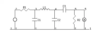
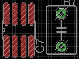
The picture below shows the basic circuit that I want to use as well as the construction. I am using the following core with around 200 windings and two 10nF ceramic capacitors to form the tank circuit.

enter image description here

Circuit Simulation

The picture below shows the FFT of the input signal from the function generator (green / channel 4) as well as the voltage measured across the tank circuit (orange / channel 1.) It can be seen that the filter does not seem to attenuate the harmonics for some reason (the third harmonic for example actually seems bigger in the filter output.)

enter image description here

During the measurement, I set the output of the function generator to around 100mV peak and I adjust the frequency to maximize the voltage across the tank circuit to ensure that I'm actually at the resonant frequency of the tank circuit.

I am not sure as to why my filter does not work properly. I thought that the ferrite core itself may create harmonics. In principle, the flux density in the core should be given by:

$$ \hat{B} = \frac{\hat{V}}{A \omega N} $$

Where \$A\$ refers to the core area. If I plug in the data for my core, I get:

$$ \hat{B} \approx 4.5\mathrm{mT} $$

That seems relatively small. Could there be another issue that I'm missing?
JRE
  • 67,678
  • 8
  • 104
  • 179
Mantabit
  • 343
  • 1
  • 10
  • can you use your signal generator (or simply a sound card! These are often pretty nice in linearity at medium volume) to generate a (pseudo) white noise signal to test the filter's amplitude response? – Marcus Müller Mar 09 '22 at 15:55
  • 2
    You might want to improve your model of your tank circuit, by the way. Try to measure the DC resistance of your coil, and in your spice model, add a series resistor of that value to the inductor. You might have to guesstimate the parasitic capacitance (inter-winding capacitance) of your inductor. Start with 40 pF in parallel to the inductor. Might want to put a series resistor with the cap, as well. – Marcus Müller Mar 09 '22 at 15:59
  • 2
    oh, and try replacing your ceramic cap with a film / mica one. These are less prone to nonlinear behaviour, which in itself introduces harmonics! – Marcus Müller Mar 09 '22 at 16:00
  • 3
    .. or at least make sure your 10n ceramic caps are NP0 dielectric rather than something horrible like X7R. – Spehro Pefhany Mar 09 '22 at 16:43
  • Hello and thanks for your replies. The dielectric of the capacitors is indeed an NP0. I am wondering if there is any literature about harmonic generated by ferrite cores for relatively weak signals (say 5mT). Obviously, 5mT is around 1% of the saturation flux density of the ferrite so the ferrite should have a fairly linear current vs voltage relationship. But what does "fairly linear" mean, does it mean a THD of -100dB or -60dB? I will try the white noise measurement. – Mantabit Mar 09 '22 at 16:59
  • Use a low-pass filter set at 1.2 x operating frequency and not a BP filter. – Andy aka Mar 09 '22 at 18:08
  • 2
    To effectively measure the harmonics, you also need a *high pass* filter before the oscilloscope. The input circuit of your scope or spectrum analyser is also non-linear, so you will struggle to measure down to -80 dB with it exposed to the full strength fundamental. 1) build filter and measure its response at 3f and 5f etc. 2) measure fundamental *without* the HPF. 3) measure harmonics *with* HPF, correct for filter response. All of this is easier with 50 ohm everything, while you have a high impedance source, but it can be done with some care. – tomnexus Mar 09 '22 at 18:37
  • You will get distortion from the inductor's core. The flux density is about 90 times below the saturation point which should be pretty good. However, you are looking at distortion components 10,000 times below your fundamental, so the distortion from the ferrite may come in to play. If it's distortion from the inductor, the distortion will increase with increasing drive amplitude. An air core inductor removes any doubt, however, that's a lot of turns even for a 1mH inductor. – qrk Mar 09 '22 at 21:13
  • Most likely the a to d in the oscilloscope is not good enough to measure that low a distortion. You need a better measurement device. – user69795 Mar 09 '22 at 21:52

2 Answers2

1

For an experiment I need to generate a sine wave which has a THD below -80dB.

At 10kHz, most decent soundcards will do that without any trouble. A function generator is another matter, if it goes up to several MHz, then it'll probably have a fast ADC with not that many bits, which isn't ideal for low distortion.

Your passive filter would need very linear components. If you use a class 2 ceramic capacitor like X7R, it will generate a large amount of distortion due to its strongly voltage dependent capacitance. Better choices would be C0G ceramic of MKP/PPS film.

Unfortunately the large inductor value needs a core, and that will also introduce distortion due to hysteresis (and saturation if it's too small). You could try a larger air gap, or maybe even an air core... but an air core inductor will become an antenna picking up magnetic fields, and the lower THD will come with higher noise.

If you want a tight, high Q bandpass, and you want low THD, then it's better to do it with opamps and without inductors. But then, the circuit is not that different from a low distortion oscillator.

Note that the usual 8-bit ADC on most scopes will not measure below -80dB THD. So you could be measuring the THD of the scope. If you want low THD measurement at audio frequencies... again, just use a decent soundcard.

bobflux
  • 70,433
  • 3
  • 83
  • 203
  • Hello and thanks for your reply. As I understand, the best option would be to use a soundcard which tends to have better THD compared to an Oscilloscope. Moreover it might be useful to dampen the fundamental during the measurement of the harmonics with a high pass as was suggested earlier (and compensate the measured harmonic value with the measured damping of the high pass filter). If I understand you correctly, the distortion from the capacitors comes from a saturation effect, e.g. if I keep the voltage across the capacitors low, they should have lower THD? – Mantabit Mar 10 '22 at 12:26
  • Yeah, the audio ADC/DAC chips in a soundcard are optimized for low THD at audio frequency. Some are better than others, but modern chips are surprisingly good. It's not necessary to remove the fundamental with a notch filter if you need -80dB THD. If you need -100dB or more, then maybe. – bobflux Mar 10 '22 at 22:00
  • Ceramic capacitors cause distortion not because of a saturation effect but because their capacitance depends on voltage. Not just DC voltage, but the instantaneous voltage on the cap. If you use these caps in a filter, then there will be AC voltage across the caps, so the capacitance changes along the waveform. So if you design your filter for a frequency, this change in capacitance causes the filter's cutoff frequency to move around with the signal. – bobflux Mar 10 '22 at 22:06
  • Note I'm talking about ceramics like X7R, not NP0/C0G ceramics. They're different materials. NP0/C0G have very stable capacitance and negligible distortion. – bobflux Mar 10 '22 at 22:09
0

You have given your self a challenge here, and you are absolutely correct in your observation that the third harmonic is increased after the introduction of your filter. Take a look at the dynamic magnetization curve of your N48 material, from the TDK data sheet:

enter image description here

You can see that there is a noticeable magnetizing hysteresis, which results in a nonlinearity of the B-H relationship as the direction of magnetization changes. This permeability nonlinearity will show up in your filter output as odd harmonics of the exciting sine wave. If you were to apply a perfectly pure sine wave to your filter, the odd harmonics would appear. You may be able reduce this effect by increasing the air gap (which will decrease the inductance) or going to all the way to an air core as @qrk has suggested, and adjusting the capacitance accordingly.

Good luck!

John Birckhead
  • 10,524
  • 1
  • 11
  • 27
  • While very true, I doubt it's the case for OP since, in order to reach those levels the H would have to be in the A/m or tens of A/m. – a concerned citizen Mar 10 '22 at 09:58
  • 1
    Of course you are right. I didn't mean to imply that the filter response follows this curve, but the curve shows that the remanence is significant and that the permeability will not be constant when the field reverses direction. Some core materials publish a "THD Factor" parameter, which would be better for predicting the effect, but N48 does not. – John Birckhead Mar 10 '22 at 13:45