0

I need to (extremely) reliably detect the status of a normally-closed DPST momentary switch at the end of a short distance of cable (max. 3m, 22 AWG).

I propose to do this with two entirely independent circuits, driven with arbitrary pulse-trains generated by an MCU. Each circuit will have a dedicated LDO to supply a higher signaling voltage (5V), which will be modulated by a MOSFET attached to the MCU. This should allow the MCU to detect mis-wiring, short to ground, short to any supply rail, short to a supply rail at a voltage higher/lower than the intended voltage, etc.

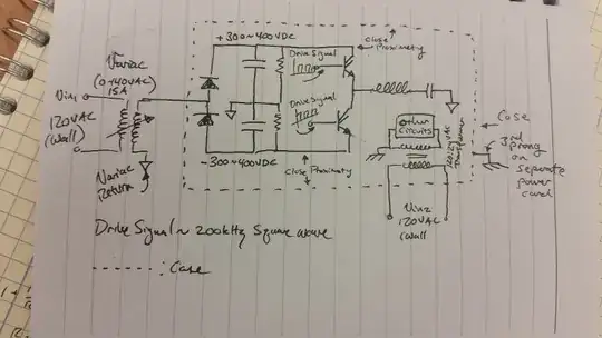
This is the high-level block diagram (apologies for the quality – too much coffee this morning):

EDIT: These should clearly be P-channel MOSFETs as high-side switches, not N-channel. Mis-drew them. Excellent catch by @brhans.

Block diagram

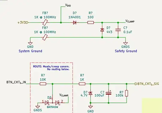
And this is the proposed input conditioning circuit (also drafted quickly for the purposes of feedback – please let me know if you spot any mistakes!):

Input conditioning circuit

My objective is that this input conditioning circuit will protect the MCU against ESD or more prolonged unintentional shorts to supply rails. The MCU will implement low-pass filtering, etc. and read these inputs with an ADC peripheral.

Overall, my questions are as follow:

  1. Is the overall concept (in particular, use of the separate LDOs) reasonable?
  2. Any feedback on the implementation of the input conditioning circuit?

Thank you for the advice and help! Really appreciate the StackExchange community.

EDIT I don't have a lot of details on the environment – it may be assumed to be a reasonably harsh electrical environment, in proximity to (smaller) brushless motors and other industrial equipment.
foxtrot
  • 167
  • 7
  • What is the application and environment that this system will be deployed in? I have the suspicion that adding all this extra signal "conditioning" and having an MCU generate pulse trains etc. will cumulatively introduce more failure points than just wiring +5V to the switch and looking at the output. For example, I do not see a watchdog timer or any other system to detect a failure of the MCU. – vir Mar 01 '22 at 17:05
  • As you are speaking of a safety critical application, are there any safety related standards that should be considered? "Extremely reliable" is very vague in these topics, one usually refers to MTBF etc. – Klas-Kenny Mar 01 '22 at 17:05
  • 1
    @vir These other mechanisms are omitted for the purpose of this diagram. There are window watchdogs, voltage supervisors, and the MCU is a safety MCU supporting up to SIL 3. This is more of a question of the electrical concept – whether the group here believes that this topology is reasonable. – foxtrot Mar 01 '22 at 17:12
  • @Klas-Kenny That's totally fair. The question is intentionally vague, in that sense, because I'm hoping to solicit feedback that might improve the design to the highest possible levels. I would love to get these functions into the range of less than 100 FIT. Preferably as close to 10 FIT as I can. But there are no directly-applicable safety standards for this specific application. – foxtrot Mar 01 '22 at 17:15
  • N-Channel MOSFETs as high-side switches ... you sure about that idea? – brhans Mar 01 '22 at 17:18
  • And why LDOs in particular - are they running from a supply which is only slightly above their output? – brhans Mar 01 '22 at 17:19
  • @brhans Ugh, you're right. I mis-drew those. They should obviously be P-channel. – foxtrot Mar 01 '22 at 17:20
  • @brhans Regarding LDOs: mostly because they need to supply almost no current, and they're very low FIT while still providing features like overcurrent/overtemp shutdown that make the circuit more robust in the hands of a downstream user wiring up the DPDT switch/cable. – foxtrot Mar 01 '22 at 17:21
  • The MCU control over the P channel MOSFETs needs work because the MCU runs at a lower voltage I assume based on this: `Each circuit will have a dedicated LDO to supply a higher signaling voltage (5V)` but also I'm failing to see why it should run on a different voltage - what's the idea behind this and, are the LDO regulators particularly "LDO" for a good reason - I see none. – Andy aka Mar 01 '22 at 17:30
  • I think you may be overthinking this somewhat. Miswiring will be discovered when the system is initially tested or after maintenance; there's no need to continually test for it. Adding a test mode to check the integrity of the connection without tripping protective features would be a good feature if it isn't already required. I have operated and maintained nuclear reactor core safety systems and they do not use this level of complexity; just redundancy and regular testing. – vir Mar 01 '22 at 17:31
  • 1
    @vir "I have operated and maintained nuclear reactor core safety systems and they do not use this level of complexity; just redundancy and regular testing." <- That is extremely cool :D So, for this application, the assumption is that it will be installed, forgotten, and possibly damaged over time – in other words, I can't rely on a human in the loop maintaining and manually testing this equipment. Which means I would like it to have built in detection and diagnosis of faults. – foxtrot Mar 01 '22 at 17:36
  • I understand your desire to have this thing bulletproof but I would definitely walk away from a project where someone wants you to design a safety critical system that will not be maintained or tested. Or at least make it easy to diagnose and repair faults. – vir Mar 01 '22 at 17:41
  • 1
    @vir I appreciate the advice – I'm thinking of this as being somewhat closer to something like an automotive application, in which you have a number of safety-related functions that need to operate correctly or detect and diagnose their faults. They can't fix themselves (obviously), but they can refuse to operate. That's how this is intended to work, as well. – foxtrot Mar 01 '22 at 17:46
  • @ksk As you can see, safety-critical means different things, depending. In those I worked, medical infusion pumps, there had to be carefully considered specified responses to every conceivable failure. Also, every single line of code through every single code branch had to be tested. And the goal is to let physics (which is always consistent) determine intrinsic safety, where possible. This isn't easy. – jonk Mar 01 '22 at 18:25
  • The crux of your question is does this concept satisfy SIL-3 ?? My understanding is SIL-3 is >= 99% Fault detection but not necessarily fault correction. (?) So the real question is what makes up 99% of all likely faults, considering environment (hostile?) voltage, power and energy levels? – Tony Stewart EE75 Mar 01 '22 at 18:35
  • @TonyStewartEE75 Yeah, that's a great way of wording it – I think I have the necessary system-level fault detection coverage, but really what I'm looking for is feedback on the specific circuit/concept outlined here. I know what types of faults I need to be capable of detecting, and I need to not destroy my I/O while doing it. Secondarily, having these circuits independent from one another to reduce the likelihood of CCF, etc. – foxtrot Mar 01 '22 at 18:49
  • If this is to prevent CCF, I would expect SIL-4, but this doesn't define the environment for expected benign faults or hostile environmental faults for V, Pwr, Energy. To simply detect the state of a DP-NC switch , can't you inject a differential microcurrent and ,measure absolute and differential voltage? – Tony Stewart EE75 Mar 01 '22 at 19:28
  • @ksk - If you don't know your environment, how do you expect to determine your FIT rate, which you said you want to drive to less than 100, and preferably close to 10? – SteveSh Mar 01 '22 at 19:29
  • @ksk - And the easiest way to achieve a low FIT number is to 1) minimize the number of parts, 2) use high quality parts (established reliability devices) and 3) choose a benign environment. – SteveSh Mar 01 '22 at 19:31
  • I concur with SteveSh. Also, trying to evaluate a design without measurable criteria is pointless – Tony Stewart EE75 Mar 01 '22 at 20:28
  • Maybe relevant: https://en.wikipedia.org/wiki/Safety_integrity_level . A company that I used to work with sometimes had to deal with "SIL-rated" components. "SIL Relay" was a phrase I used to hear from time to time. – Solomon Slow Mar 01 '22 at 20:31
  • In case the DP is there for redundancy purposes, you should perhaps use a switch with mechanical latching/forcibly guided contacts. Or are they two separate signals? Also you need external pull resistors on the MOSFET gates. And pull downs on the button inputs obviously, but those can be internal in the MCU. – Lundin Mar 02 '22 at 09:26
  • If you're worried about SPF (single point failures), why don't you use/make a 3-pole single throw switch with one side of each switch tied to GND and with simple pull-ups on the input to the MCU, and use a 2 out of 3 voting function to decide the position of the switch? – SteveSh Mar 02 '22 at 15:09

1 Answers1

2

(You give no environmental or application details. Please can you edit these into your question.)

For your proposed circuit...

You have practically no load on the switch so it's passing a tiny current all that way. If it's to be 'extremely reliable' then a higher current makes it more resistant to radiated transients it might pick up. You give no environmental or application details at all but a guess/RoT value would be 10 mA.

For an alternative circuit...

You have a DPDT switch i.e. a double-pole changeover switch. So connect both poles of each switch to your cable.

That way, your MCU gets positive confirmation that the switch is in one position or another, rather than confirmation that switch is in one position but only assumption that it's in the other position. I have a used this schemes for similar applications, such as for relay contacts in a fault-intolerant dual-redundant design (warship firing system).

The below circuit shows the connections for one half of the switch. This delivers at least 2.8 V to the MCU with the 5 V down at 4.75 V. It puts approx. 8.6 mA through the switch when at 4.75 V.

Shorts of the switch drive output can be detected, along with the switch position. If your MCU has an ADC input, use that to detect the SW_DRV_SHORT_N voltage instead/as well as a GPIO input.

schematic

simulate this circuit – Schematic created using CircuitLab

TonyM
  • 21,742
  • 4
  • 39
  • 62
  • 1
    This is nice, and simpler. Thank you for the suggestion! Going to play around with it in PSpice. – foxtrot Mar 01 '22 at 17:50
  • you said (talking about the switch) that "a higher current makes it more resistant to radiated transients it might pick up". I wasn't aware that mechanical switches were susceptible to radiation... – SteveSh Mar 01 '22 at 19:33
  • 3
    @SteveSh The switch isn't, the 3 m wires are – Neil_UK Mar 01 '22 at 19:52
  • My comment still stands. I've never seen a radiation effects analysis that included wires. Do you have an example of one? – SteveSh Mar 01 '22 at 20:11
  • 1
    @SteveSh: I suspect there is some confusion here about EM radiation vs "hard" radiation. By "radiated transients" TonyM was most likely speaking of EM. Wires are absolutely included in EMI analysis, as they act like antennas. – Ben Voigt Mar 01 '22 at 20:30
  • @Ben Voight - You may be right. TonyM said "radiated transients", which I took to mean a radiation effect. If that's the case, I apologize for the confusion. – SteveSh Mar 01 '22 at 20:58
  • @SteveSh, am back now and yes, EMI rather than atom bombs :-) – TonyM Mar 01 '22 at 21:11