I have been studying about op amps and there is something I can't get my head around. The thing is, when assuming an ideal op-amp, one of the restrictions we obtain is that the voltage in both the inverting and non-inverting inputs is the same. But while operating in the linear region, the output voltage is a function of the difference. Thus, the output voltage should be zero, or that's what I interpret. I know about the assumption that the gain is assumed to be infinite and see why the output voltage would be non-zero but very vaguely. Could someone please explain this a little bit further, especially these assumptions?
-
See https://electronics.stackexchange.com/a/468422/11684 – Scott Seidman Feb 25 '22 at 14:52
-
1This has been asked many times before. Just search `[operational-amplifier] ideal gain input zero` on the site and you'll get lots of hits. – Null Feb 25 '22 at 16:50
-
@Null, I think the link you posted has good answers, but the ones in this question are in my opinion, worthy of keeping, as there are some answers that are different from the ones there. However, thanks for the link. – Gaston Castillo Feb 25 '22 at 17:43
-
@ScottSeidman, in spite of the fact that it is a good question and has some intersection with mine, I think they are different, but thanks for pointing out as it will be useful – Gaston Castillo Feb 25 '22 at 17:45
-
@GastonCastillo Nothing will be deleted if one question is closed as a duplicate of another. – Null Feb 25 '22 at 18:20
-
https://electronics.stackexchange.com/questions/441184/op-amp-virtual-ground-principle-and-other-doubts/441207#441207 – G36 Feb 25 '22 at 18:34
-
In mathematical terms, zero times infinity isn't zero, its an [indeterminate form](https://en.wikipedia.org/wiki/Indeterminate_form). You need to solve the limit as the terms approach the extremes in order to find out what happens. – mbrig Feb 25 '22 at 23:57
7 Answers
The input difference for an ideal opamp is not zero by coincidence but because the opamp is contained in a circuit where the output can make it zero using feedback and the polarity of the inputs is such that the output swing for any input difference will work towards making the inputs equal again. That puts the circuit in a stable equilibrium that will, due to the opamp being ideal, be maintained instantly for any input change. If the feedback has the wrong sign, the equilibrium is unstable: in theory with an ideal opamp and no noise whatsoever, and unstable equilibrium can also be maintained but there is no way you can do so in practice.
So the hidden assumption for any opamp circuit is that it has been designed in a manner where negative feedback will make the output instantly correct any situation where both inputs would be unequal.
That is not a feature of the ideal opamp itself; it is merely the condition the ideal opamp needs in order not to blow up around your ears like, say, an ideal voltage source shorted by an ideal wire would.
You aren't considering feedback. You're thinking of it as feeding two signals to the input independently of the output (i.e. open loop with no feedback).
With negative feedback, the inverting input is driven to be equal to the non-inverting input, but that doesn't mean the output required to accomplish this is zero.
A super obvious example is a buffer:

simulate this circuit – Schematic created using CircuitLab
If I put 1V in the input, the output tries to drive the inverting input to also be 1V. The voltage difference between the opamp inputs is then zero. Does this mean the output is zero? Clearly not because in this case the output is equal to the inverting input; And since the inverting input is equal to non-inverting input you have a buffer. Magical.
If you then start sinking the output to ground in the feedback loop through resistors or other components, then that saps away voltage from the output before it gets to the inverting input so the output has to be even higher to achieve a given voltage at the inverting input. Then you have an amplifier.
- 54,733
- 4
- 67
- 153
Here is my short answer: Assuming Vdd=10V and Vss=-10V
- Real opamp, case 1: Ao=1E4 >>>> Vd,max=10V/1E4=1mV
- Real opamp, case 2: Ao=1E5 >>>> Vd,max=10V/1E5=0.1mV
- opamp model : Ao=1E9 >>>> Vd,max=10V/1E9=10nV
- IDEAL model: Ao infinite >>>> Vd,max=10V/oo=0V
Comment: In most cases, during calculation of values for gain and/or resistors we can assume Vd=0 (even for real opamps) because the error caused by this simplification will be much smaller than errors caused by resistor tolerances and other uncertainties (simplified formulas which neglect opamps input and output resistances). Assuming Vd=0 (and , at the same time, infinite open-loop gain Ao) simplifies the calculation.
- 24,857
- 2
- 23
- 52
In an ideal op-amp, the open-loop gain is infinite hence, when negative feedback is employed, it seeks to make both inputs have the same voltage. The reference input (the non-inverting input) sets the demand and, the inverting-input (subject to negative feedback) is driven by the feedback to have the same voltage as the reference input.
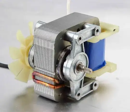
It's a control system; you set the demand on the non-inverting (reference input) and the output rises or falls to a level that makes the inverting-input equal the non-inverting input. Would a motor control system with an error amplifier cause you to scratch your head: -
Once you recognize that the op-amp (error amplifier above) is part of a control system, you can ditch the motor and feedback potentiometer and wire directly like this for a unity gain buffer: -
Sure, it's hard to wrap your head around something that has infinite gain doesn't need to have a difference voltage to drive the output to a particular value so, maybe consider that it isn't so ideal; maybe it has an open-loop gain of 1 million and say that the two inputs were equal to within a few microvolts. Would that cause you consternation or can you live-with that? After all, a few microvolts error for an op-amp is about as good as it ever gets.
Hey you might as well think of it having an open-loop gain of 1 billion and the two inputs would be equal to within a few nano volts.
- 434,556
- 28
- 351
- 777
\$V_{IN}\$ is NOT the quantity that the opamp amplifies. The opamp equation is $$V_{OUT}=A(V_{+} - V_{-})$$
That means $$V_{+}-V_{-} = \frac{V_{OUT}}{A}$$
Notice \$V_{OUT} = V_{-} + \frac{R_1}{R_2}V_{-}\$.
When you apply \$V_{IN} \gt 0\$, the output \$V_{OUT}\$ slowly starts increasing;
the voltage at \${V_{-}}\$ node also starts increasing;
the output keeps on increasing and becomes constant when the difference at the opamp inputs equal \$\frac{V_{OUT}}{A}\$:
$$V_{IN}-V_{-} = \frac{ V_{-} + \frac{R_1}{R_2}V_{-}}{A} \\~\\ \Rightarrow V_{-} = \frac{V_{IN}}{1+\frac{R_1+R_2}{AR_2}} $$
That expression is very close to \$V_{IN}\$!
- 1,100
- 11
- 25
-
Now I understand everything much better. Seeing this derivation allows me to see clearer the fact that as A goes to infinity, the closer V_out gets to V_in. Thank you very much – Gaston Castillo Feb 25 '22 at 17:48
The ideal op-amp behavior assumes infinite gain. That is:
- \$ (Vp - Vn) * Av = Vout \$
Or
- \$ (Vp - Vn) = \frac{Vout} {Av}\$
Where Av is the gain (infinity for an ideal op-amp) and (Vp - Vn) is the voltage difference.
On the face of it, it seems you can have only 3 states of Vout: -infinity, zero, and +infinity. Which is nonsensical. How could such a device even be useful as an amplifier?
We have to look at it differently. As Av tends toward infinity, the voltage difference tends toward zero. That ‘tends toward’ is kind of a sleight-of-hand, which nonetheless should give you a hint that this is a limits problem. And in fact that’s exactly how it’s treated mathematically (see the OCW paper, below.)
On the other hand, a non-ideal op-amp (gain < infinity) will have some voltage difference, that is, Vout/Av, while an ideal op-amp will have zero difference based on that limits trick.
The other key point to keep in mind is the effect of feedback, that is, there is a path from Vout to Vn through some kind of network. This feedback makes the op-amp work very hard to swing Vout to a voltage that will nullify any input difference.
So when we model an ideal op-amp that has feedback, we assume Vp = Vn and work from there to analyze each network including the feedback from Vout to determine the voltages and currents. We don’t get hung up on that infinite gain stuff.
And for a non-ideal one? Same way in all but the most critical cases, because op-amp gain is typically very large and so the input voltage difference is very small.
More here: How does this op-amp config work as a voltage follower?
And here: How is op amp output not zero if inputs have the same voltage?
Further Reading
A very good MIT OpenCourseWare tutorial on op-amps: https://ocw.mit.edu/courses/electrical-engineering-and-computer-science/6-071j-introduction-to-electronics-signals-and-measurement-spring-2006/lecture-notes/22_op_amps1.pdf
- 49,832
- 2
- 47
- 138
-
Really good answer, liked the emphasis on the concept of feedback and distinciton between the ideal and non-ideal op-amp. Thank you very much – Gaston Castillo Feb 25 '22 at 17:50
-
1But it should be clear: "Nullify any input difference" is valid for the IDEAL opamp only (infinite Aol). For any other cases (finite Aol) we may ASSUME Vd=0 (without a remarkable error), but in reality we always have Vd in the lower mV or µV range. – LvW Feb 25 '22 at 18:21
-
I added some links that dive into this a bit more. The OCW link gives full details. – hacktastical Feb 25 '22 at 20:19
-
1Lots of problems in basic analysis of electrical circuits go away when you use the mathematical idea of a limit to describe ideal components. This is why when you buy an ideal component, it always comes with a warning label ;) – richardb Feb 26 '22 at 14:53
For comparison, a real op-amp works by looking at the voltage across its inputs and using that information to determine what to output. In other words, the output is a function of the inputs.
On the other hand, for an ideal op-amp operating in its linear region, the voltage across its inputs is always zero, and so the op-amp doesn't receive any information. For an ideal op-amp, the output is not a function of the inputs.
So how does an ideal op-amp know what to do?
You can think of an ideal op-amp as being a magical device which looks at the entire circuit and magically predicts what it needs to output in order to prevent the input voltage from changing. Obviously, such a magical device can't exist in real life, but as long as we're just analyzing circuits by hand, nothing is stopping us from playing pretend.
- 2,991
- 12
- 21


