8

This problem is decades old but I do not see a direct answer to it on this site. I want the following:

enter image description here

This circuit just allows to check the state of the button from inside the micro-controller. Nothing fancy. My questions:

  1. Is there anything better than this simple design?
  2. Is the value of 100 kilo ohms resistor adequate for our days CMOS devices, like dsPIC30FXXXX and not a high power application?
Kirill Kobelev
  • 316
  • 1
  • 16

5 Answers5

6

First, a lot of microcontrollers and digital signal controllers will have internal pull up resistors. Here's an example, an Atmel ATMega164. ATMega164p GPIO port

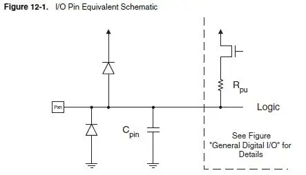
There will typically be a register that allows the internal pull ups to be turned on and off. Due to variations in the fabrication process, these internal pullups come in a very wide range, and are not a good choice if you need very close control over current draw in ultra low power applications. If keeping component count low is important, this is an easy way to do it. Using internal pull ups for hardware debounce would not be a good idea, since it's not possible to predict their exact value.

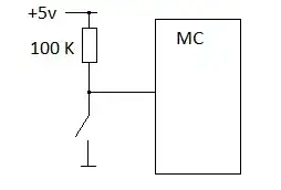
Whether the 100\$k\Omega\$ value is adequate depends. If it's just a switch that will be periodically flipped by a user, then 100\$k\Omega\$ would be a good choice for minimizing power consumption. For things that are going to switch more rapidly, such as rotary encoders, the process I would go through is

  1. Find maximum sink current in data sheet
  2. Calculate a pull up value using Ohm's Law
  3. Choose a standard sized resistor a few sizes bigger, depending on the speed actually needed
  4. Test and see if the resistor size chosen gives the required rise and fall times
  5. Adjust accordingly

So if the maximum sink current per GPIO pin were 10 mA and operating at 5V: \$R=\dfrac{V}{I}=\dfrac{5V}{10mA}=500\Omega\$. Keeping this R value small as possible will allow for the sharpest edges and highest switching frequencies.

Matt Young
  • 13,734
  • 5
  • 34
  • 61
  • Are you saying that because of wire/trace capacitance you'll have an RC circuit that will cause signal propagation delays to the uC, and that with a larger R these propagation delays can actually cause misreading of a rotary encoder? – angelatlarge Mar 15 '13 at 00:11
  • Yes, parasitic reactances are just a fact of life that need to be dealt with more and more as frequency increases. – Matt Young Mar 15 '13 at 00:14
  • Interesting! I am confused though: assuming that paracitic capacitance is less than 1 uF, given a resistor of 100k Ohms and assuming 0.1uF parasitic C, we get a time constant of around 23mS (input = 5V, output =4.5V). In other words in a 5V circuit, the uC will see 4.5V on the input in an up-going pulse in less than 25ms. For the uC to miss that (under the assumption that it isn't polling), the encoder would be generating pulses at 40Hz or so. Is that something we should worry about? – angelatlarge Mar 15 '13 at 00:28
  • Parasitic capacitance is typically in the nano or pico Farad range. This becomes a problem with rotary encoders at higher speeds. Consider an optical encoder that puts out 24 pulses per revolution, and is spinning at 1500 RPM. The output square waves are going to be 600Hz with a period of about 1.2ms. This is still slow enough that the minimum sized pull up would be unnecessary, but 100\$k\Omega\$ would make for rise and fall times that are unlikely to be acceptable. This is worth a question on its own. – Matt Young Mar 15 '13 at 01:01
  • True and true. I was thinking of manual rotary encoders. – angelatlarge Mar 15 '13 at 01:05
4

You can get simplier than that.

Just use an internal pull-up/pull-down resistor in your microcontroller.

100k is adequate, but internal pullups could to be a bit lower in some MCUs, for example in AVR atmega8 it's 30-80kOhm for reset pull-up and 20-50kOhm for all the other I/O pins.

miceuz
  • 5,523
  • 3
  • 39
  • 49
  • You cant't say that 100k is adequate. There is no universal receipt, you have to compute the value according the the MCU and the device driving the pin at the other side. – Blup1980 Mar 15 '13 at 08:46
  • 1
    The person asking the question specified a push button. I don't see a problem with this answer. – mjh2007 Mar 15 '13 at 14:34
1
  1. Is there anything better than this simple design?


    Better can't be answered without specific criteria to measure against, which you haven't provided. In most cases, the topology you show is fine. Two variations might be "better" depending on the situation:

    Many microcontrollers have internal pullups on some of their pins. These are meant for exactly this kind of situation. The resistor is then internal to the micro and you set a bit someplace to enable it. The only external part required is the just the pushbutton itself.

    Another useful variant to keep in mind is for low power designs where the button might be a switch that can be closed for long periods of time. In that case you want to minimize the long term average current thru the pullup resistor. You make it as big as possible, but there are limits to that and drawbacks for making it too big. Instead, you switch the pullup on for just a few µs at a time to take a button reading. If you check the button every 1 ms and the pullup is on for 10 µs, then the average pullup current is reduced by 100x. With a external resistor you use another pin to drive the top side of the pullup. With a internal pullup, you enable/disable it in firmware as needed.

  2. Is the value of 100 kilo ohms resistor adequate for our days CMOS devices, like dsPIC30FXXXX and not a high power application?


    I have already answered this at length here.

Olin Lathrop
  • 310,974
  • 36
  • 428
  • 915
0

Better than that simple design? Yes. Throw a cap on it and you have a simple hardware debounced switch.

enter image description here

The Capacitor would be a common 0.1uf ceramic cap. The Resistor would be a 10k. This site has the full details on why. In short, a debounce circuit prevents the microcontroller from false registering multiple presses when you press the button. The Resistor/Capacitor setup smooths the button's mechanical bouncing so that it's a steady transition.

Passerby
  • 72,580
  • 7
  • 90
  • 202
  • Electrolytic caps don't like being shorted out. I regularly use 100nF which works fine for my applications. – jippie Mar 15 '13 at 07:54
  • 1
    @jippie the symbol was what the image had, but a 100nf or 0.1uf ceramic is what is needed. – Passerby Mar 15 '13 at 10:59
  • 3
    This is not a good debouncing circuit. First, this only debounces a break, not a make. When the button is pressed, the cap is shorted immediately. Second, the time constant of 1 ms is too short to be much use. Third, this should only be fed into a Schmidt trigger input. Normal inputs don't like slowly rising signals. Just leave off the cap and do the debouncing in firmware, which you'd need to do anyway even with the cap. – Olin Lathrop Mar 15 '13 at 12:02
  • Yes, on make the cap is immediately shorted, but any recharging because of bounce is low pass filtered, removing any effects of the bounce. Perhaps more accurately, debounce on make is a very different mechanism than debounce on break. One ms is too fast though. I don't like using this circuit for any number of reasons. However, if you're driving an interrupt with the pin in question, debouncing in firmware often isn't the best solution. Moving to a DPST and debouncing with an SR flipflop is a pretty good method for that case. – Scott Seidman Mar 15 '13 at 20:03
0

EDIT - the comment i made below was meant to follow-up what Olin had said later about the circuit with a capacitor to supposedly add debounce. I'm sorry it seems to appear in the wrong place - maybe someone can fix this because I'm obviously too blind or stupid to see how i should have done it!!

I agree with Olin - it does not provide good debounce. I would also add that shorting the capacitor out can cause a big surge of current that can reset the microprocessor if PCB layout is not really good. Some switches need a wetting current to operate correctly and reliably and 100k may be too high for some switches (especially membrane switches).

Andy aka
  • 434,556
  • 28
  • 351
  • 777