4

Is it reasonable to float an AC signal on top of a HV DC bias with a HV Capacitor and low input bias current OpAmp?

The idea is that a fixed frequency AC signal (~1V pk-pk) comes from the left, is coupled to whatever DC bias voltage GND_HV1 is on the right, and buffered by the OpAmp.

Some protection diodes prevent damage to circuitry on the left/right from rapid voltage changes in GND_HV1.

A voltage stable cap is used to prevent capacitive coupling changes based on the GND_HV1 bias.

If the design is feasible, is there any advantage to using a FET based OpAmp over a BJT one?

Most capacitively coupled designs (discrete or monolithic) discretize and encode the input signal before coupling, and decode after coupling. This introduces delays and noise on the coupled signal. I figure there's a reason I've not come across this topology before, what is it?
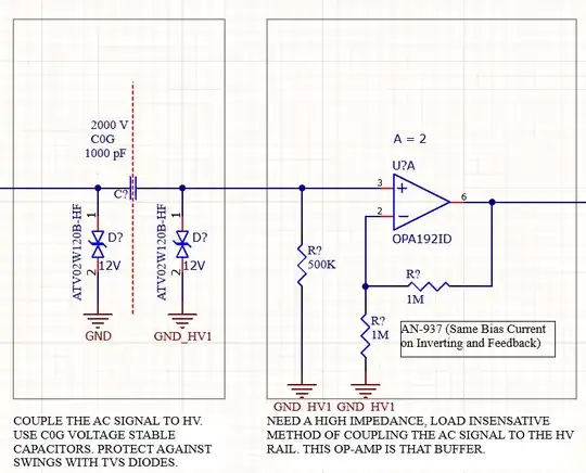
enter image description here

  • 2
    What's "high voltage" in this scenario? You've shown a 2kV capacitor but a 12V TVS on the line. – Polynomial Feb 22 '22 at 22:02
  • 1
    D? is toast. (Well, one of them) –  Feb 23 '22 at 14:59
  • @polynomial High voltage here is 1500V. They are two different grounds. The HV ground floats at whatever HV is (1500v). I’ll edit the question to clarify. – user3527854 Feb 24 '22 at 00:32
  • @user3527854 Right. Well it won't be 1.5kV if you try to stick a 12V TVS between it and ground. Otherwise it seems vaguely sane, although I personally wouldn't trust my life to a single capacitor; I'd want an isolated opamp in there for safety. – Polynomial Feb 24 '22 at 00:34
  • 2
    Obvious but: 1500V on a 2000V cap needs careful looking at. A DC rated cap MAY suffice in well controlled circumstances, but real life is liable to not comply. TVS's help (of course) but ensure cap design is rated for worst case clamped transients. || Presumably corner frequency of C? and R? is suited to frequency concerned. || You can buy 'analog' isolators where the hard HT work is done internally. Using other people's advance expertise versus saving $ is a tradeoff that you have to decide on. – Russell McMahon Feb 28 '22 at 12:49

1 Answers1

1

I would not count on a blocking cap by itself to do galvanic isolation at 1500V. A large transient could overwhelm it (even a ‘Y’ cap that is intended to fail open.) Thats probably why you don’t see this used in practice, at least not at that voltage. (It’s common with normal powerline voltage however.)

More about X and Y caps here: What is an "XY" rated safety capacitor, exactly?

And that TVS on the left side is… a smoke generator. Maybe not your intention.

Power line modems use high-pass filters to block the mains frequency and pass the modem signal (modulated on a carrier), but you don’t have benefit of that here being as your power is DC. Still, there might be a solution from there.

Perhaps modulate your AC as common-mode and filter for that using some kind of magnetics.

It might also be feasible to use optical, assuming the LED bias can be worked out. Again, using a carrier helps.

The general class of problem is, as you probably guessed, like a powerline modem. Look to that space for solutions that can meet necessary safety criteria.

Related: Coupling the powerline communication modem for 3 phase line

hacktastical
  • 49,832
  • 2
  • 47
  • 138