4

enter image description here

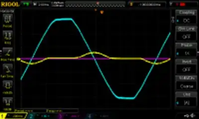
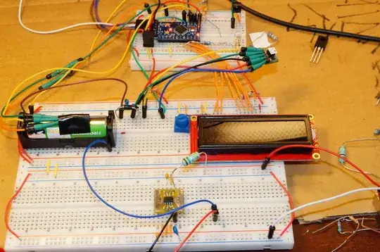
I designed a class C amplifier. I used a signal generator for the input signal. For the resonance circuit, I used a 3.3uH coil and a 480pF capacitor. The transistor is BC547-C.

The resonance frequency for these values is 3.99 MHz. Due to the tolerance values of the circuit elements and the use of breadboard, the maximum output amplitude was realized at 3.45MHz. This is an expected situation.

There are three questions that bother me.

  1. How did the amplitude of the output become greater than the source voltage? As you increase the coil value (for example 10mH,) the amplitude of the output becomes larger at the resonant frequency.

  2. The output resistance of the signal generator is 50 ohms. Impedance matching is essential for maximum power transfer. For this, I calculated the input resistance of the transistor. If I'm not wrong, I calculated the Rpi resistor as 480ohm. The calculation is available in the picture. I wanted to select the base resistance small to bring the input resistance closer to 50 ohms. I tried values like 100ohm, 330ohm, etc. However, the maximum output amplitude was achieved when the base resistance was 1k. Why did the maximum amplitude occur with thr 1k value?

  3. If the amplitude of the input signal is less than 0.7 volts, this circuit would not work because the transistor needs about 0.7V for the base to be triggered or to conduct. How can this problem be solved when the signal amplitude is below 0.7 volts? How can the circuit be operated?

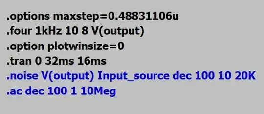
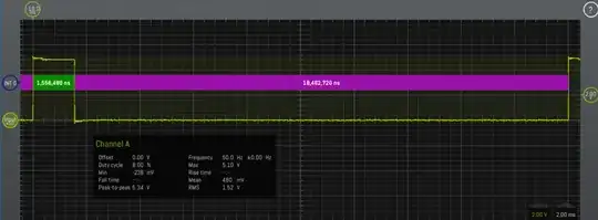
edit:LTSpice simulation image.very different with results from real experiment. enter image description here

enter image description here

enter image description here

OzGtZ t
  • 105
  • 5
  • These are all great experiments, and great questions. I don't have time to give all the answers. You could learn a lot from all three concepts you have 'wrong'. I hope people don't close this question before you get good answers. – Neil_UK Feb 19 '22 at 07:40
  • Neil_UK ,thank you. – OzGtZ t Feb 19 '22 at 07:44
  • Thought. Class C amplifier has "generally" an inductor between base and ground. Interesting, I will try your schematic. – Antonio51 Feb 19 '22 at 08:11
  • As I can see, there are different modes of behavior. The first one is when the input voltage peak is <300 mV peak with a small gain. Voltages and currents are almost quasi-sinusoidal. Measured input impedance is about 800 Ohm, so 1k// "hie" ... Ib current is low, but exist. – Antonio51 Feb 19 '22 at 09:12
  • Which voltage source? – Andy aka Feb 19 '22 at 10:20
  • @Andy aka ..........................................dc – OzGtZ t Feb 19 '22 at 10:48
  • 1
    That simulation has no DC bias on the transistor base, it is only AC coupled to the signal source. For Class C it would generally be biased at 0 V. Leaving it unconnected for DC is not the same as 0 V bias. Bias for Class C is usually accomplished by having an inductor from base to ground. This can be an RF choke, the secondary of an RF transformer, or an inductor that is part of a filter. At the very least you should have a resistor, so that the base isn't floating for DC. – GodJihyo Feb 19 '22 at 16:04
  • 1
    Also, get into the habit of putting a load on the output of any amplifier simulation. Leaving the output coupling cap hanging like that will generally cause you headaches. Put a resistor from the cap to ground, preferably the expected load impedance. – GodJihyo Feb 19 '22 at 16:12
  • Also note that the circuit shown on the breadboard and the simulation schematic do not match, the 1k resistor is on the opposite side of the capacitor. – GodJihyo Feb 19 '22 at 19:30
  • @ GodJihyo, GodJihyo,Thanks for your attention. I misplaced the resistor and capacitor in the simulation. I swapped them. Now there is a more stable output signal. – OzGtZ t Feb 19 '22 at 22:51
  • @GodJihyo how do you float in base DC?there is no DC coming into the base. The base has no connection with the DC. Am I thinking wrong? – OzGtZ t Feb 22 '22 at 21:46
  • @OzGtZt If the base has no connection to DC it's 'floating', which means the only bias the transistor is going to have is from CB leakage and the cap charging through the BE diode junction. With the resistor on the other side of the cap it will be more stable, but you usually see some kind of inductor there, either to ground or to a source of bias voltage. Note that a class C amp is going to generate some amount of distortion, even with a the tank circuit on the collector, this is why you almost always follow one with a low pass filter. – GodJihyo Feb 22 '22 at 22:37
  • @GodJihyo I added a 47uH coil between the base and the ground. Also, the output of the signal generator, in other words, the source resistance is 50ohm. I calculated the input impedance of the transistor as 600ohm. Then I matched the impedance. As a result, I got a 17V amplitude signal from the output. But I am not sure if I calculated the input impedance correctly. Can you calculate it too? – OzGtZ t Feb 22 '22 at 23:57

2 Answers2

5

How did the amplitude of the output become greater than the source voltage?

  • The collector is connected to the DC voltage source via an inductor
  • This means that the average voltage level at the collector equals the DC voltage source
  • This is all about inductors; if you don't follow this bit then go and study inductors and inductor volt-seconds
  • OK, it may be a few millivolts lower due to collector current and non-idealities in the inductor
  • Assume it's the same for very practical reasons
  • Because DC collector voltage equals the supply voltage, any AC waveform on the collector will "peak" higher than the DC supply and "valley" lower than the DC supply. This will be symmetrical (go study inductors and volt-seconds)
  • The lowest undistorted level is nearly 0 volts (say 0.5 volts)
  • The highest undistorted level is nearly twice the supply voltage (say 2*Vcc - 0.5 volts)
  • Maximum p-p output voltage is nearly twice the supply DC voltage

Why did the maximum amplitude occur with the 1k value?

Because you never accounted for something - try simulating to see what you get and don't forget about the output impedance of the signal generator and miller capacitance of the transistor.

How can this problem be solved when the signal amplitude is below 0.7 volts? How can the circuit be operated?

Operate it as a linear class A amplifier.

Andy aka
  • 434,556
  • 28
  • 351
  • 777
  • ,thank you.I understood the answer to my questions 1 and 3.For the second question, you said try the simulation.I simulated the circuit in LTSpice program. But I am getting results that have nothing to do with the results on the board. – OzGtZ t Feb 19 '22 at 14:18
  • Be precise and tabulate result (A) against sim prediction (A). I cannot guess what your numbers are. What signal generator did you use and what output impedance does it have and, did you mimic that in your simulation properly? – Andy aka Feb 19 '22 at 14:34
  • ,The output impedance of the signal generator is 50 ohms.To model this, do I need to connect a 50 ohm resistor in series with the source? – OzGtZ t Feb 19 '22 at 14:50
  • 1
    Yes you need to do that. Also note that I have no idea what the node names are in your simulation pictures. Try naming a node like "Vout" or something so that it's clear. In other words your sim pictures currently shown in your question are meaningless. – Andy aka Feb 19 '22 at 15:14
  • @OzGtZt if we are done here you should choose an answer and formally accept it; this is what is expected from you on this site. – Andy aka Mar 23 '22 at 09:19
2

How did the amplitude of the output become greater than the source voltage?

For this, I calculated the input resistance of the transistor. If I'm not wrong, I calculated the Rpi resistor as 480ohm.

If the amplitude of the input signal is less than 0.7 Volts, this circuit would not work.

Some pictures to see that it works. Almost sinusoidal. (Others to come).
It can work at a low level, although BJT is not really "on" as in digital circuits.
(See Ebers-Moll at "low-level" input ...).

Pictures : for generator amplitude input < 300 mV peak
One do not forget that an LC tank has "infinite" impedance at resonance.

NB: The addition of L2 and R4 (as well as the corresponding load to an oscilloscope probe x10) does not seem to have a "significant" impact on the curves resulting from the previous simulations, apart from a "small" lowering of the frequency of work.

AC Analysis to see "resonance" frequency

enter image description here

Simulated input impedance calculation
Input impedance should be ~ 800 Ohm.

enter image description here Transient analysis to see behavior -> amplitude output ... Current driven. See low Ib current.

enter image description here

See the bigger current into the inductor.

enter image description here

And for some other levels

enter image description here

enter image description here

enter image description here

Antonio51
  • 11,004
  • 1
  • 7
  • 20
  • thank you. I simulated the circuit in ltspice but it is very different with the behavior in the circuit.I have attached the simulation images to the question, can you take a look? – OzGtZ t Feb 19 '22 at 14:23
  • Your curves seem "likely". However, in my simulation, distortions appear as soon as the amplitude exceeds 0.6V at the input. I will add also the current in the inductor. – Antonio51 Feb 19 '22 at 14:41
  • What are the base, collector and emitter current values in your simulation? Can you write the values you found? When I run the circuit in the ltspice program, the collector current is 9pA. Isn't this a ridiculous value? – OzGtZ t Feb 23 '22 at 00:08