4

I'm taking my first electronics course in my EE program, so I'm just delving into the world of Spice programs. l

I've been asked to use LTspice to design a unity gain buffer amplifier using the LTC6085 in LTspice, and simulate it for a transient response of the output voltage with an input voltage source of a trapezoidal pulse with an amplitude of 1 V, rise and fall time of 1 usec, and a flat top width of 3 usec. We were then asked to compare the input to the output voltage on a plot.

I already completed the project, but I'm curious about one thing I noticed in the graph of the function.

my ltspice buffer amplifier

I noticed that there is a lot of overflow in the circuit simulation graph, and I'm not sure why this is. Could someone explain why this overflow is here?

My instructor already approved the circuit and gave me a high grade (I'm not asking for homework help, I'm just looking to understand why this overflow exists.) As far as I know, buffer amplifiers have equal input and output voltage. Is this overflow something that should/could be corrected? How would I do it?
JRE
  • 67,678
  • 8
  • 104
  • 179
  • 7
    I think you mean "overshoot": "*go past (an intended stopping or turning point) inadvertently.*" – Transistor Feb 18 '22 at 17:24
  • 1
    Note that the output should not be the same "thing" ... if the input amplitude was 10 times lower ... because the "bandwidth" is "larger" for "small" signals ... See my answer on this post: https://electronics.stackexchange.com/questions/577088/op-amp-speed-bandwidth-vs-slew-rate/577093#577093 – Antonio51 Feb 18 '22 at 18:44
  • It looks like they did a god job with he model. – a concerned citizen Feb 19 '22 at 09:45

2 Answers2

7

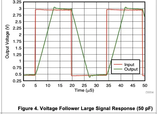
When the input signal slew rate exceeds what the opamp is capable of the output cannot follow the input accurately and it amplifier output will change at a constant slew rate determined by its design until it reaches input voltage.

When the input stops changing the output catches up but then overshoots. Th amount of overshoot will depend upon the stability of the amplifier that will be affected by the capacitance loading of the amplifier.

This is normally detailed in opamp data sheets as large signal response slew rate. Attempting to make the output move faster than this rate will cause this effect.

All opamps have some limitation in this parameter but higher frequency opamps will be able to slew faster.

enter image description here

enter image description here

LM324 datasheet

Kevin White
  • 32,097
  • 1
  • 47
  • 74
6

The LTC6085 (the part in your question) shows this in its data sheet: -

enter image description here

So, if you'd studied the data sheet it shouldn't be unexpected. Also, a lot of op-amps will do this; especially when configured as a unity gain amplifier because the feedback brings it closer to being unstable more than most other simple configurations.

If you ran it at higher gain, the overshoot would be less pronounced. If you add more load capacitance you can usually make overshoot a lot worse until you reach the point where the amplifier design naturally turns into an unwanted oscillator.

I also think you are asking a bit much of this device (maybe not studying the data sheet): -

enter image description here

Your supply is +/- 15 volts and this is not a good choice given that the maximum supply range is 6 volts. All bets are off when this happens. I'm surprised you didn't get picked-up on that by your teacher: -

enter image description here

My instructor already approved the circuit and gave me a high grade

Time to find a better instructor maybe?

Andy aka
  • 434,556
  • 28
  • 351
  • 777
  • Thank you for letting me know about the supply voltage mistake; I set it to now be between 3 and 6 volts. Does that work better? (Also thank you for your help with the overshoot question; that makes so much more sense!) – LightningParab Feb 18 '22 at 19:28