1

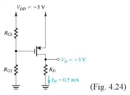
I stumbled upon the following paper while looking for ways to calculate a specific value for the pullup/pulldown resistor for the gate of a MOSFET. I see several calculations for Rg. Is that the pullup/pulldown resistor for the MOSFET?

Related see this Q
rdivilbiss
  • 919
  • 1
  • 7
  • 12
  • 1
    In Fig 4.24 these would be called bias resistors because they set the operating conditions of the amplifier, AKA it's "bias point". Although I can see your confusion, because pull ups and pull downs are placed in the same location. The different names are given according to the purpose or intent not the position, as confusing as it seems. – placeholder Mar 14 '13 at 04:40

1 Answers1

3

The lecture deals with DC steady state analysis of the MOSFET. Pull-up and pull-down play the role when there is switching or transient behavior.

I wouldn't call RG1 and RG2 in the lecture pull-up and pull-down. In the lecture, they form a resistor divider, which sets the gate voltage. They may have as well drawn an ideal voltage source between gate and ground.

enter image description here

Nick Alexeev
  • 37,739
  • 17
  • 97
  • 230
  • If you drew it as an ideal voltage source, it would only be a DC circuit at a constant bias - you do need the voltage divider as resistors to increase the input impedance to something that you can drive. It would be more accurate to say a voltage source and a resistor in series. – W5VO Mar 14 '13 at 04:23
  • @W5VO Can't say that I follow. Just in case, I've updated my post with the image I was referring to. It would be safe to assume that Vdd = +5V is an ideal voltage source. The gate current is negligible. The voltage divider generates a constant voltage. The ideal voltage source with the same voltage (which I was talking about) would be between the gate and ground. – Nick Alexeev Mar 14 '13 at 04:41
  • He's just saying that this is an amplifier, if you had an ideal voltage source it would be so stiff that you'd not be able to drive against that. If it is Ideal then it must have the equivalent series resistance. – placeholder Mar 14 '13 at 05:26
  • @rawbrawb What would drive against a voltage source connected between gate and ground, biasing the gate? This is DC, so even the gate capacitance is not in the question. May be, I wasn't clear, and W5VO misunderstood me. I'll wait for him to chime in. – Nick Alexeev Mar 14 '13 at 05:33
  • What is the use of an amplifier whose input is shorted to small signal ground? If you have replaced the resistors with an ideal voltage source, it's OP resistance is "zero" this is the input to an amplifier, that means it is shorted to ground (small signal wise) = no input. – placeholder Mar 14 '13 at 05:49
  • WOW! Stirred up a (friendly) hornet's nest. But the discourse is enlightening. I think I'll leave this open for now. I might learn some more I should know. – rdivilbiss Mar 14 '13 at 05:58
  • @rawbrawb Read the example problem in the lecture. Example N27.4. Please. Notice that it doesn't ask for an amplifier with an input. It asks for a *fixed* circuit, which operates at a particular current and voltage. – Nick Alexeev Mar 14 '13 at 06:13
  • Oh, it's not a hornet's nest. In the context of that question yes, you can put in a voltage source as you say. I won't speak for @W5VO but I understand **WHY** he said that. IF you are experienced, you look at that and say, that's an amplifier! why short the gate? It is an exercise in calculating bias currents and operating points. Probably the next set of questions be to calculate \$ G_m \$ and then inject a signal into that input. But that's a guess. – placeholder Mar 14 '13 at 06:27
  • @rawbrawb Pretty close guess. [They are gradually building and amplifier stage.](http://whites.sdsmt.edu/classes/ee320/notes/320Lecture28.pdf) – Nick Alexeev Mar 14 '13 at 06:49