7

I have circuit where I need to fire electromagnetic actuator fast. If I need to go faster strike I need to increase voltage. But what about freewheeling inductor energy.

In circuit A the energy is "shorted" with diode and current decay is pretty slow, but voltage at collector of T1 doesn't really go higher than Vcc.

Circuit B have higher freewheel voltage and will decay faster. But does make additional voltage (zener) at collector of T2

Circuit C (modified half bridge) dumps voltage back to Vcc. So it should be fast decay with no additional voltage at collector of T3.

The actuator in question have resistance of 1.5 Ohm, and inductance 0.3mH when open and 0.35mH when closed. It need to reach 6A peak under 200 microseconds and freewheel in 800 microseconds.

I don't know if my assumption is correct. Does I miss something fatal? What voltage I need?

enter image description here

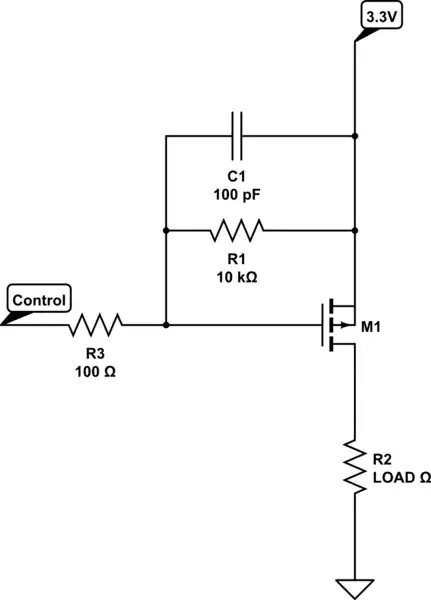
For test I use this circuit as seems to be better alternative as circuit 2: enter image description here

eSlavko
  • 171
  • 2

4 Answers4

2

Circuit 3 don't work as you expect -- bottom of coil is clamped by D3 to VCC+0.7, top of coil to VIN-0.7 ==> coil has 1.4 V only.

You can't reverse V across a coil like that without another transistor.

If you use circuit 2, you may have difficulty finding a suitable zener that can handle 6 A. You can instead connect the zener + D2 to the transistor's base (depending on the base driver) so that the transistor actually dissipates the energy.

jp314
  • 18,395
  • 17
  • 46
2

Circuit 1 is not good because of the long time to dissipate the energy.

Circuit 2 is not good because energy dissipation is in a part that is not designed for this load.

Circuit 3 is not good because bottom of the L3 will make positive voltage when transistor is not conducting, and will freewheel through D3, D4.

Quick and dirty solution: circuit 1 + resistor in series with the freewheeling diode. Resistor can be designed to dissipate large power, and selection of the correct resistor allows to choose how fast to dissipate the energy.

Expensive but efficient solution: circuit 3 but all 4 semiconductors are transistors, forming a full bridge, or H bridge. This allows to take the energy back into the battery, or better still, a capacitor. Quickly charging the actuator and discharging it, not wasting all the energy that went to charge it.

2

Do you need something as this?
A bit complicated by the fact that you want a "fast" recovery.

enter image description here

The updated with two MOSFET IRF540.

enter image description here

Edit: Added this, better?

enter image description here

Antonio51
  • 11,004
  • 1
  • 7
  • 20
  • Huh that's complicated circuit. And seems to need driver with two output. – eSlavko Feb 17 '22 at 08:00
  • It is impossible to do otherwise with a single transistor, given the very limited "recovery" time. this circuit must obviously be "reworked", because it is only a "principle". – Antonio51 Feb 17 '22 at 08:40
0

The actuator in question have resistance of 1.5 Ohm, and inductance 0.3mH when open and 0.35mH when closed. It need to reach 6A peak under 200 microseconds and freewheel in 800 microseconds.

If you are free-wheeling in a longer time than you are charging then, circuit B is OK for this. To achieve 6 amps in 200 μs will require a voltage supply probably in excess of 20 volts. This is because of the 1.5 Ω resistance will drop 9 volts when 6 amps is flowing.

What voltage I need?

Probably in excess of 20 volts. At 20 volts and an ideal inductor, V/L x 200 μs = 11.42 amps but, of course you have to compensate for the resistive volt-drop so, I estimate about 20 volts is needed. OK, that's an over-estimate because 16 volts will achieve this in 200 μs: -

enter image description here

Image from this hyperPhysics calculator.

Andy aka
  • 434,556
  • 28
  • 351
  • 777
  • 1
    I do quick test on bench and seems that I need at least 30V. I realised that I need power stroke in 200uS, not max current.... – eSlavko Feb 16 '22 at 18:40
  • I have no idea what a power stroke is and how many amps it requires. Please be clear. – Andy aka Feb 16 '22 at 18:43
  • In 200us I need to physically move actuator. With test I find that if I set power supply to 30V and limit at 6A with 200uS pulse I got needed stroke in actuator. Freewheel with 600V supressor diode. (I use 1200V/100A IGBT and signal generator for test) – eSlavko Feb 16 '22 at 19:29
  • Try it at 20 volts to see what happens. – Andy aka Feb 16 '22 at 20:07
  • @eSlavko With a 600V supressor diode the decay will be very fast. A 60V zener would give you ~50us decay. – Bruce Abbott Feb 16 '22 at 20:59
  • I do test with items I have at home. And the IGBT is way to big (as my palm) so now I need to minimize to fit in device. I have space for aprox 3 items of TO220 size., – eSlavko Feb 17 '22 at 07:56
  • "I set power supply to 30V and limit at 6A" -- don't trust the power supply current limit during such a short time. It will likely have a large output capacitor (1000's of uF) and this is 'outside' the current limit circuit. At very fast activation times, the eddy currents induced in the core make the effective inductance of the core less than might be measured at a low frequency. Current will build up, but won't generate an energizing magnetic flux until these day currents decay – jp314 Feb 17 '22 at 19:26