3

I am looking for some advice on the direction of this project, I am a mech eng, who likes to tinker with electronics as a hobby.

I want to build a on/off MOSFET switch for a 20s4p li-ion battery pack, including a pre-charge circuit to limit the inrush current and preventing sparking on the connectors.

Most of the examples I have found are only rated for 12s (50.4 V) batteries, but I need to switch ~84 V at 150 A continuous, ideally with the lowest possible leakage current in the off state to prevent draining the battery when not in use.

examples - https://github.com/msglazer/Anti-Spark_Switch

https://github.com/VinFar/High-Side-NMOS-Antispark-Switch

I would also like to implement a soft-start circuit to use a momentary push button, push to turn on, then push for 3 seconds to turn off.

Maybe also an auto switch off after 30 mins if no current has been drawn. I have looked at using an ATtiny with the sleep mode, which consumes very little power.

I am looking at using this Directfet - IRF7769L1TRPBF, putting a few in parallel to have a good headroom of current capability.

Any advise on how to design a circuit to switch 150 A at ~84 V and how to approach this would be great!

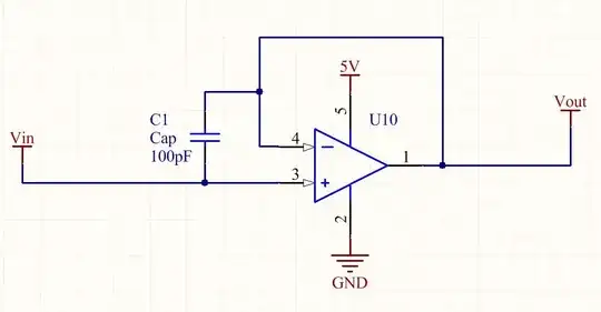
Edited with proposed circuit diagram without MCU control yet.

SwitchControlCircuit

Edit 2

Replaced the toggle switch with push buttons. I found this LTC7001EMSE#PBF gate driver, which can work at over 100 V, so can I just use the main Batt voltage to drive the gate with this? It says it's a high side driver, will this work?

https://everycircuit.com/circuit/6035721594601472

SwitchControlPushButtons

ocrdu
  • 8,705
  • 21
  • 30
  • 42
JackDavies
  • 31
  • 4
  • 2
    This is really a whole system design issue. What are you allowed to change? The battery pack? The device being powered up, or do you just want to design something that interposes them and manages pre-charge? Take note that Xt90's are available with anti-spark resistors. These seem to work. Would certainly be easier. – user57037 Feb 13 '22 at 21:32
  • Also be advised that FET's are on backorder and allocation with lead times in some cases exceeding 52 weeks. So when you are selecting FET's, make sure you are selecting FET's that are actually available, and I would advise you to order them and get them in your hand before you order your circuit board. – user57037 Feb 13 '22 at 21:35
  • 1
    You can use a 3-pin power connector with two long pins for pre-charge and ground, and a shorter pin for power. The only difference between the power pin and precharge pin is that precharge has a series resistor so that connects first and then is soon after shorted across by the short power pin. Something similar could be done with a three-position switch where the center position is pre-charge. – DKNguyen Feb 13 '22 at 21:37
  • 150A at 84v is 12.6kW. What is using this power? – Bruce Abbott Feb 14 '22 at 21:59
  • Application is a high power ebike/motocycle. Will also be used for a boat jet drive which is pretty much 100-150A continous. – JackDavies Feb 15 '22 at 10:50
  • Please use one gate resistor per MOSFET to avoid oscillation. – winny Jul 26 '22 at 20:19
  • For precharge, we would need to know the capacitance of the ESC to which the battery pack will be connected. This will determine the energy that will need to be transferred, and how fast this needs to be done will determine the power dissipated. Once connected, the series MOSFET(s) would need only be able to carry the 150A without overheating. It's advisable to limit current through any individual device to about 20-30A because of lead size and PCB tracks, so maybe four to six 76A devices like https://www.mouser.com/datasheet/2/240/ixys_s_a0003807071_1-2272482.pdf. – PStechPaul Aug 28 '22 at 08:49

4 Answers4

2

Nothing wrong with your approach, but there is a reason we don't do it that way in the large battery industry: the standard solution is far simpler and it adds galvanic isolation (which your solution does not).

It uses two contactors, a precharge relay, and a precharge resistor (typically 10 Ω, 50 W).

Precharge circuit

Davide Andrea
  • 16,164
  • 4
  • 33
  • 62
  • 1
    Hi Davide, unfortunately space requirements are rather tight so a more compact solution is required. However very interesting to learn, thank you for sharing. – JackDavies Feb 15 '22 at 19:38
0

I am looking at using this directfet - IRF7769L1TRPBF putting a few in parallel to have a good headroom of current capability.

I wouldn't recommend putting FETs in parallel if you can avoid it. I've done this when desperate but it can cause all kinds of problems with load sharing and makes your system less robust.

I need to switch ~84 v at 150 A continuous

Digikey has this 110A, 100V FET available to ship immediately for ~$4USD/each. Keep in mind if you use NMOS you will either need a gate driver to hook up to the high side of the load or to hook it up to the low side of the load. If you want a high side switch with no gate driver, you can use this PMOS (pricey but simplifies your system) with this circuit topology:

schematic

simulate this circuit – Schematic created using CircuitLab

I would also like to implement a soft start circuit to use a momentary push button, push to turn on, then push for 3 seconds to turn off. Maybe also an auto switch off after 30 mins if no current has been drawn. I have looked at using an attiny with the sleep mode, which consumes very little power.

For soft start, this can be achieved using a hardware RC circuitry depending on the sophistication of the behavior you want there. For more sophisticated soft start, you may want to PWM into the RC. For some of these other features like 3s to turn off, 30min auto switch you are better of implementing those in software. The ATTiny is an excellent choice. I've shipped Li Ion products with them and you can get their consumption well below 20uA. They also have solid timing features that can wake them up from sleep to do tasks periodically like turn off your auto switch after 30mins.

Last but not least, whatever FET you select you'll have to make sure you have robust heat sinking. There are a lot of ways to approach this. If you use a TO-220 you'll have a through hole to install a heat sink. Since you're a mech E I'll trust you can figure that part out ;).

Edit: Adding circuit requested by OP with ability to turn on micro at t=0 w/ pushbutton (It can be done w/ RC but there's a trade-off of user ergonomics for each imo this is superior). Upon button press the micro starts up and holds up the NMOS to VCC+ until conditions are met such that the micro no longer wants to draw current and resets GPIO to 0V (commits suicide).

schematic

simulate this circuit

Edit #2: Common Comparator Circuit w/ Hysteresis that's suited for this application. Simply voltage divide down the battery voltage, carefully tuning the reference against the input voltage and put the output into the ATTiny's digital input to sense when your Undervoltage threshold has been reached.

enter image description here

jimBeaux27
  • 29
  • 6
  • Hi Jim, thank you very much for the detailed answer, really appreciate it! I was looking at the directfet package (IRF7769L1TRPBF) as vertical space is quite limited in my battery design, and I like the thermal heat sinking ability with an aluminium plate on the top, clamping down on the PCB and also serving as a case. Would you mind elaborating on the reason its not good to parallel them? I see this used quite a lot in other designs. – JackDavies Feb 14 '22 at 14:31
  • I am fairly comfortable with programming and working with microcontrollers, so once I have a good idea of the power electronics part then I should be able to implement the “smart” features. The other issue I am trying to solve is how to power the ATTiny from the 85v supply, I found this reg (ZXTR2005Z-13) with a 30mA output, which should be enough for the ATTiny, is that a good way to go? – JackDavies Feb 14 '22 at 14:31
  • I have built a very similar circuit to this before, and it worked very reliably with a simple toggle switch. Just need to replace the toggle switch with the ATTiny in principle. - https://user-images.githubusercontent.com/12124823/39087400-6783e32a-456e-11e8-9646-04920302eb20.png – JackDavies Feb 14 '22 at 14:32
  • Finally do you think there is a way of achieving 0 power draw in the off state to prevent draining the battery if left for a while? Another option would be to detect if the voltage was too low and put it into some kind of emergency shutdown. I guess the least complicated method would be to put the ATTiny into deep sleep which should last a while. Thanks again for your help! Jack – JackDavies Feb 14 '22 at 14:32
  • Hi Jack, no problem! The part you mentioned looks pretty good it should good enough. Just keep in mind that all of the current ratings etc are contingent on good board design. The reason I dislike parallel is because it is difficult to guarantee they all turn on at the same time, share the same current etc and it creates more points of failure. – jimBeaux27 Feb 14 '22 at 15:51
  • The Linear reg ZXTR2005Z-13 could work. The biggest figure of merit you'll care about are Vin max & Iq (quiescent). If the latter is too high it could drain your batteries. It looks like it's in the 100's of uA at 48V which is OK but not the best I've seen. Note you'll incur more Iq as your voltage goes up. It's going to depend on the capacity of the cells you're using and other items. I've used the TLV70450 for lower voltage applications and gotten below 10uA *with* the ATTiny in sleep mode. But that application required years of shelf life. To use the TLV70450 you'd have to... – jimBeaux27 Feb 14 '22 at 15:57
  • ...pull off of one of the cell taps (i.e. don't go to 20s, go to 3s or even 2s). Just note that will put uneven wear on your cells and potentially cause imbalance over very long periods of time. – jimBeaux27 Feb 14 '22 at 15:58
  • As for 0 current...let's consider less than 100nA "close enough". This is definitely doable. You'd need the ATTiny circuitry to have the ability to "commit suicide" and shut itself and everything else off. You could achieve that by creating an RC + FET circuit such that it turns on a series FET to your linear regulator at t=0 (insertion) but then is controlled by a GPIO and can be severed once sufficient conditions are met and recognized by your MCU. – jimBeaux27 Feb 14 '22 at 16:01
  • @JackDavies see edit above for more details on how to sever current flow after a timeout/software conditions are met. – jimBeaux27 Feb 14 '22 at 16:14
  • Hey Jim, epic thank you! As far as I understand this is what the system flow is; (1) SW1 is pressed, powering the ATTiny (2) ATTiny then boots up and pulls the gate of the switching MOSFET high enabling the battery current flow (3) ATTiny then enters sleep mode, with a watchdog timer of 30min & button press input interrupt – JackDavies Feb 15 '22 at 10:17
  • (4) After 30mins ATTiny wakes up and checks if power is flowing, if no then switches Batt MOSFET low and then cuts its own power (5) If a button press is detected it only counts it as pressed after 3s, (can use milis() and a state machine etc.) then switches Batt MOSFET low – JackDavies Feb 15 '22 at 10:18
  • I found this regulator - MAQ5281-5.0YMME-TRVAO with a very low quiescent current of 6uA. I will start trying to lay out this circuit in full, let’s see how far I get! – JackDavies Feb 15 '22 at 10:18
  • Thinking some more maybe it is enough to just sense voltage < min voltage and shutdown the pack that way. Should be easier to measure pack voltage with a voltage divider and read it with the ATTiny. – JackDavies Feb 15 '22 at 10:49
  • Some commentary: Re 2) Almost however, it's unclear if you mean the pmos or nmos. The NMOS turns on with logic *high* from the micro (positive VGS). When that happens it creates current flow that turns on the PMOS which requires *negative Vgs*. That is achieved due to the current flow through the resistor network. Re 3) Not quite. I would not use a WDT for this task. WDT is specifically for making sure your system's while(1) loop isn't stuck somewhere. The period is variable but it's on the order of a few hundred ms to a few seconds... – jimBeaux27 Feb 15 '22 at 12:15
  • ...I'd use a general purpose timer which can be scaled up to whatever timeout you want. I've achieved many hours on the ATTiny. 4) Yes however you'd have to have a current sense amplifier feeding into an ADC to know that OR you'd need some kind of digital circuit with a threshold 5) YES I was just going to mention this. It's an easy way for you to achieve that design objective. I'll add it might be user friendly to add an LED to indicate to the user you've "accepted" the press. – jimBeaux27 Feb 15 '22 at 12:21
  • That part looks good just make sure you tap off the batteries at the appropriate point and be careful of Vin_max which is sort of high in this application! – jimBeaux27 Feb 15 '22 at 12:22
  • Yes you can achieve that with a simple comparator circuit. Be sure to use the feedback resistor for hysteresis! Otherwise it's a hair trigger. – jimBeaux27 Feb 15 '22 at 12:24
  • The "1K pulldown" gate driver will not work for these kinds of huge voltage/current switching. First don't forget to clamp that gate, because now the fet will just die immediately at switch on, due to violation of Vgsmax=20V. Also, Investigate the SOA curve for this fet. At these voltages and currents, you will need to switch in around 100us to avoid damage to the device. build a proper gate driver. Select mos for best SOA operation besides the Rds, and make sure the driving circuit is up to par. Optionally use a floating gate driver to use Nfets at the high side if needed. – Thijs Feb 15 '22 at 13:34
  • Yea fair point. I am not making any claims with regard to appropriate values you should double check all those and make sure the ratings are met. That said, no parts have been selected so how do you know Vgsmax=20V? I just quickly used circuit lab's default values. It's important to make sure you comply with all the ratings and understand how the circuit + math works not just copy paste. – jimBeaux27 Feb 15 '22 at 14:39
  • The PSMN5R0-100PS you suggested and IRF9530 both have the maximum Vgs in the datasheet. When the OP is connecting his 84V, R1 will drop about 76V (with M1 conducting) and the fet is destroyed. You could try to combat this by using clamping diodes across R1 limiting that to 10-15V. But be aware that R2 is now dropping 70V, about 5Watts for 1K. Increasing the resistance to 10K creates a manageable power dissipation but will also result in even worse switching performance. For 150A switching you can't just pull down the gate with 10K! The gate driver page you link to can be a good place to start – Thijs Feb 15 '22 at 15:15
  • Yea you'd have to tune the *ratio* of the two resistors and the absolute values based on the SOA Vgs and as you point out power dissipation. If you're not in an SMPS and doing a simple load switch it should still be doable but you can use a gate driver too like I said earlier. – jimBeaux27 Feb 15 '22 at 15:22
  • I have started laying out the circuit, attached an initial circuit diagram (above) of just the basic switching without MCU control. This circuit has been built before by quite a few people so I have good confidence it will work - I am getting a bit in over my head with the other solutions! I am now trying to add in the MCU control circuitry, any tips would be greatly apreciated. Thank you for your continued input! – JackDavies Feb 15 '22 at 17:42
  • The low side switching makes things easier for you, good choice. An MCU pin will not be able to sink and source enough current to switch 5 power fets in microseconds. When switching 150V 84A this becomes important so you don't damage the fets due to SOA violation. Paralleling fets for better SOA will generally not work great is the current sharing during switching isn't great, although steady-state power dissipation can be significantly lowered with this method. A cheap gate driver like UCC27517A (still in stock) will be able sink and source large amounts of current to switch the gate(s),.... – Thijs Feb 16 '22 at 10:43
  • provide the needed level translation to reach lowest Rds(on), and buffer the signal at the same time. Layout and design principles are shown in the datasheet. Many other IC's could work for you as well. https://www.ti.com/power-management/gate-drivers/low-side-drivers/products.html Look over here for more drivers and read the datasheets to get tips on best-practices for board and schematic design. Be sure to add (small!) gate resistors to smooth out any ringing and better parallel switching. Just add a gate supply voltage with enough decoupling cap. to supply the gate charge(s) – Thijs Feb 16 '22 at 10:44
  • Thanks for the input guys, I am definitely now looking at implementing a gate driver. Do you think using a gate driver rated for the Batt voltage will simplify things, or is there a better way I am missing? I edited my post with the driver I found, just replacing the bottom switch with the MOSFET driver. – JackDavies Feb 19 '22 at 22:07
0

This is a non-trivial problem, and not one that can be answered here, unfortunately.

For perspective, consider the mechanical analogy.

At 150A, we're talking wire about 9mm dia. So say we have a shaft 9mm dia. It's spinning at 6000 RPM with 20 N.m torque. You have, well, about "this much" space to construct a clutch between shafts. You must use materials rated maximum 150°C; exceed this and... the oil burns, materials melt or gall together, whatever. How do you do it?

This is probably an unfair comparison, because the active area inside the transistors is much smaller than the active area of a clutch. Well, the clutch does experience surface friction, but it can be made of conductive materials like copper (at least, immediately behind an arbitrarily thing friction surface, if copper is unsuitable); it can also be directly fluid cooled (or indeed fluid as the active element, as in a viscous clutch), while transistors can't. On the other hand, there's likely more inertia in a fully mechanical system (shafts, bearings, gears..).

Point of reference, transistors can dissipate up to a few joules of energy (essentially the single avalanche rating), on time scales of 10s of µs. At long time scales (approaching steady state), up to some hundreds of watts -- if fully heatsunk. Somewhere inbetween lies the pulse width and peak power that this application will experience. So, maybe more than a few joules can be handled, and a peak power more than a few hundred watts, but somewhere they meet in the middle, you can't have unlimited of both.

You're probably precharging on the order of 10 or 100J of capacitors in the ESC, which needs a comparable dissipation in the transistors. So, it doesn't look good. And you certainly can't take too long to start (or stop), if it's under load at the same time (which is implied by giving the switching current): you then have to dissipate some large fraction of full load power, on top of charging the capacitors.


I have created a circuit for my own purposes, which is able to switch up to 30V 20A, using a single transistor, and can do so for an extended period of time, about 100ms -- that is, while dropping significant voltage, without overheating the transistor. (Another, more robust element dissipates the power, and a temperature sensor stops early if it overheats.) But this is much too complicated of a circuit to describe in an answer here (it uses high frequency switching), and scaling it up to higher power levels is even less trivial.

What you seek is possible, but it will require real engineering time to create.

Tim Williams
  • 22,874
  • 1
  • 20
  • 71
0

I think it is possible to use several NMOS devices in parallel to provide a controlled pre-charge of the capacitors in the ESC from the 85V battery pack. The following simulation shows just two 100V 137A MOSFETs with 4.2 mOhm RgsOn. This circuit assumes 500 uF in the ESC, and the two MOSFETs in parallel exhibit a voltage drop of 315 uV at 150A. A simple DC-DC converter provides about 24 VDC for gate control, which is divided down to 12V by two 5k resistors, and a 1 uF capacitor provides about 200 uSec turn-on delay. If desired, a microcontroller could apply PWM to the gates with an optocoupler. Exact values will need to be adjusted as needed, consulting the SOA curves for the devices. Although the MOSFETs can handle 137 amps, it would be better to use four to six in parallel to avoid having to use very heavy copper traces on the PCB. And these MOSFETs are only about $3 each.

Precharge circuit simulation

PStechPaul
  • 7,195
  • 1
  • 7
  • 23