6

I am trying to gain some intuitive understanding of the following circuit:

schematic

simulate this circuit – Schematic created using CircuitLab

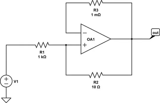
This is a simple voltage follower with a trace short between the output and inverting input. There is also a feedback path to the non-inverting input with a substantially higher resistance. So I would assume that virtually the feedback is entirely negative, and the circuit should behave just like a simple voltage follower. Indeed, the operation point seems to reproduce V1 as output voltage.

However, when simulating in LTspice, I observe a tremendous a noise originating from R2. Now the thermal noise of R2 would be about 0.41 nV/rtHz. And the circuit gain is 1 as mentioned before. But LTspice reports 41 nV/rtHz as output noise and attributes virtually all of it to R2.

Why is the noise of R2 gained by a factor of R1/R2?

The noise of R3 is amplified by the same factor, although it is not in this feedback path.

Why is the noise of R3 gained by a factor of R1/R2?

winny
  • 13,064
  • 6
  • 46
  • 63
tobalt
  • 18,646
  • 16
  • 73
  • It might be helpful if you draw a circuit model showing the noise sources as shown in this reference Noise Analysis in Operational Amplifier Circuits: https://www.ti.com/lit/an/slva043b/slva043b.pdf. The isolation of the noise source might give insight into the noise amplification factor. – SystemTheory Feb 11 '22 at 17:32
  • 1
    What model are you using for the op amp in LTspice? Are you certain that it is not oscillating? – Elliot Alderson Feb 11 '22 at 17:39
  • The noise you see is due to R1 I reckon. It's 100 times higher than R2 and the noise is 100 times higher than that of a ten ohm resistor at 30degC AND R1 is a hundred times higher than R2. Coincidence maybe? – Andy aka Feb 11 '22 at 17:47
  • @ElliotAlderson Its a default UniversalOpamp level 1. The opamp itself is noiseless. Operation Point and Transient looks steady. – tobalt Feb 11 '22 at 17:51

1 Answers1

6

Any voltage generated across R2 due to noise will cause an imbalance in the voltages at the two inputs of the opamp.

The output will then move in such a direction to counteract this imbalance.

Because of the attenuation from the output to inputs caused by the ratio of R1 and R2 the output must move about 100 times as much to compensate.

A similar effect is seen for any noise generated by R3.

Noise from R1 experiences an overall gain of unity.

It is very rare that a configuration such as that shown would be used in any practical circuit for the reasons you have found. However, occasionally it may be a good solution to improving stability in a circuit by intentionally reducing the loop gain, even if it does worsen the noise gain.

The problem comes under the general term "noise-gain" where the gain for noise may be significantly different from the gain from the wanted signal. It is especially a problem in some circuits, such as trans-impedance amplifiers where the capacitance of a device such as a photodetector can cause the noise to be amplified out of proportion to the photodetector signal.

Kevin White
  • 32,097
  • 1
  • 47
  • 74
  • Thanks. It sounds so logical that it seems embarassing to have asked in the first place - the sign of a good answer . However wouldn't a voltage across R1 cause the same imbalance and response Noise gain of R1 seems to be ~1 according to LTspice. – tobalt Feb 11 '22 at 18:20
  • @tobalt - the noise gain of R3 is also about 100. If for example you replace R3 with a 1V battery the voltage across R2 would have to be 1V for the opamp to be balanced. This would require 100V across R1 resulting in 101V at the output from a 1V signal at R3. – Kevin White Feb 11 '22 at 18:26
  • 1
    @tobalt - oops. Yes the noise gain of R1 is unity. It is indistinguishable from voltage at the input V1. Any noise from R1 is attenuated by a factor of 101 to the non-inverting input, then multiplied by 101 to the output giving an overall gain of unity. – Kevin White Feb 11 '22 at 18:29
  • `It is very rare that a configuration such as that shown would be used in any practical circuit for the reasons you have found.` The problem is that sometimes it cannot be avoided: consider a voltage follower with R3=1mohm, R2=1Gohm. Usually this will be fine, but if your source impedance is 10 Gohm, the noise suddenly increases a lot. To not amplify noise, R2 should be always higher than the source impedance, which becomes challenging for electrometer designs. – tobalt Feb 14 '22 at 13:29
  • @tobalt - In an electrometer R2 would be non-existent. – Kevin White Feb 14 '22 at 16:57
  • R2 exists always. The question is how large it can be made. – tobalt Feb 14 '22 at 17:49
  • @tobalt - There is rarely any feedback from the output to the input. There will be leakage to ground or supply. That leakage can be femto-amps on a modern electrometer. – Kevin White Feb 14 '22 at 23:04