0

I'm new to electronics and I'm coming from a programmers perspective so sorry if this is obvious.

text][1

This is a voltage division circuit (just a simple example from wikipedia.) R2 leads directly into the ground. How does R2 have an effect on the circuit then? If all the electrons entering R2 just go straight into the ground then couldn't R2 just not be there?

Is it just that only some electrons enter R2 and the rest go to Vout? If so, why? What makes them avoid R2?

I know it's doing something but I'd appreciate if someone could explain exactly what is happening rather than just refferring to Ohm's law saying that voltage is proportional to resistance.

JRE
  • 67,678
  • 8
  • 104
  • 179
Krys
  • 29
  • 1
  • 4
  • 13
    You should probably search for Ohm's law. – Scott Seidman Feb 10 '22 at 21:39
  • 1
    But the answer is in Ohm's law. R1 pulls output to some voltage that happens to be Vin, R2 pulls output to some voltage that just happens to be 0V. – Justme Feb 10 '22 at 21:40
  • 6
    Electrons do flow through R2, and in so doing generate a voltage across it. That voltage will be Vout minus the ground voltage of zero, or simply Vout. Changing the value of R2 will change the current through it and therefore Vout. – td127 Feb 10 '22 at 21:50
  • 11
    Don't think about electrons, just conventional current. Electrons flow from ground upwards in this circuit, conventional current flows down. – Finbarr Feb 10 '22 at 21:51
  • Because the other side of the voltage source is also connected to GND. – user57037 Feb 11 '22 at 00:04
  • If you've never done it before, I highly recommend opening up Falstad's circuit simulator and building this circuit in it. For Vin, use a 1-terminal voltage source, and for Vout, just use a wire that's only connected at one end. (Or, even better, put in a 2-terminal voltage source, and use the positive terminal as Vin and the negative terminal as ground.) Try replacing R2 with a wire and see what happens. – Cassie Swett Feb 11 '22 at 01:52
  • Note that with the usual Vin >0, electrons flow _out_ of the ground. They're negatively charged. – MSalters Feb 11 '22 at 12:57
  • @MSalters - the classical equations like Ohm’s Law don’t express electron flow. They deal with the flow of charge, which by *convention* (see below) is positive to negative. – hacktastical Feb 11 '22 at 16:43
  • Without R2 there's no reason for anything to go to Vout. – Chris Strickland Feb 13 '22 at 01:29

8 Answers8

19

Ground is just a point in the circuit that we choose to call "Zero Volts". It has no magical properties.

Your circuit could be re-drawn as:

schematic

simulate this circuit – Schematic created using CircuitLab

Peter Bennett
  • 57,014
  • 1
  • 48
  • 127
9

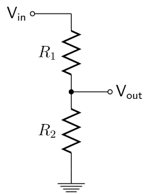
In your example, we assume no current flows to \$Vout\$, it's only a measurement point. Pretend it's literally just a point floating in space with no connection except to the junction of \$R1\$ and \$R2\$.

Also, the current flows in a loop, by convention (more below) from \$Vin\$, through the two resistors, through ground, then back to whatever is creating \$Vin\$ (a battery, say.) Ground is just a reference to zero volts.

With that out of the way, we know that each resistor has its own voltage drop. The sum of these voltage drops will be \$Vin - GND\$, or just \$Vin\$.

You can also see intuitively that \$Vout\$ will depend on the ratio of the two resistors. If \$R1\$ is equal to \$R2\$, then the proportion of the voltage drop is equal, so \$Vout = Vin/2\$. As \$R2\$ decreases its voltage drop also decreases, while \$R1\$ voltage drop increases.

How do we analyze it? Ohm’s Law, and a couple of other laws.

In a series circuit like this one the current in any part of the circuit is the same. That's Kirchhoff's Current Law, or KCL, as applied for simple current loops.

Kirchhoff's Voltage Law, or KVL, states that all the voltage drops in the circuit must add up to the total voltage. Based on KVL, we know that the sum of the voltage drops of all the elements equals \$Vin\$.

With these tools in hand, let’s get cracking.

We begin by finding the series circuit current using Ohm's Law as:

  • \$ I = \frac E R\$

with total resistance \$R\$ being the sum of \$R1\$ and \$R2\$. We plug those in and solve for \$I\$:

  • \$ I = (Vin - 0V) * \frac {1} {R1 + R2} = {Vin} * \frac {1} {R1 + R2}\$

Based on KCL, we know that the current through each resistor is the same:

  • \$ I = I_{R1} = I_{R2}\$

So we can solve for \$Vout\$ with Ohm's Law again:

  • \$ E = I*R\$

We use KCL to substitute the total current \$I\$ for \$I_{R2}\$, and finally calculate \$Vout\$:

  • \$ Vout = {I} * {R2} = [Vin * \frac {1} {R1+R2}] * R2\$

or,

  • \$ Vout = Vin * \frac {R2} {R1+R2}\$

which you may recognize as the voltage divider equation.

What if some current were to flow into \$Vout\$? We'd modify the equation to reflect that, using a generalization of KCL that states that the currents flowing into a point equals the currents flowing out.

Finally, a word about electron flow and current.

Apropos:

enter image description here

From here: https://xkcd.com/567/

Current flow from positive to negative is called conventional current. Don't worry too much about it, the classical equations like Ohm’s Law, KCL and KVL still work so long as you stick with the, um, convention.

If 'twas guid enough fur James Clerk Maxwell, 'tis guid enough fur ye, laddie.

Here’s another thing to think about. Electrons do ‘flow’ in a circuit, that’s called electron drift. It’s kind of slow, relatively speaking, on the order of cm per second in a conductor like copper. And indeed, they drift from negative to positive.

Related: Does the voltage difference have an effect on the electrons' speed?

We think about electrons when we talk about the atomic theory of materials like batteries, semiconductors and vacuum tubes. That’s the very origin of the term ‘electronics’, a legacy JJ Thomson left us in 1897, some 50 years or so after Maxwell published his unified theory of electromagnetism. Before Thomson, no one really knew what an electron was, let alone its charge.

Charge on the other hand propagates at some significant fraction of the speed of light. Charge is the ‘electro’ side of electromagnetism, and is what we analyze when we’re talking about basic circuits like this.

So from a Maxwell point of view, it’s perfectly valid to say that charge flows from positive to negative, at nearly the speed of light. And it creates a magnetic field as it does so.

So how does charge flow? That’s the realm of quantum mechanics. Look into Feynman diagrams for a gentle, elegant introduction. Try here: https://web.mit.edu/dikaiser/www/FdsAmSci.pdf

hacktastical
  • 49,832
  • 2
  • 47
  • 138
4

schematic

simulate this circuit – Schematic created using CircuitLab

Figure 1. A potentiometer (right) is a variable version of the potential divider (left).

Consider the potentiometer (a volume control for example). By adjusting the wiper from bottom to top any fraction of Vin can be selected. It should be clear that at the bottom Vout will be 0 V and at the top it will be Vin. 40% of the way up Vout = 0.4 Vin.

  • If we omit R2 we will have R1 in series with the supply voltage.
  • If we short circuit R2 then Vout will always be 0 V.

Tip: forget about electrons for dealing with practical circuits. Just think of current flowing from + to -. It's the way we all work.

Transistor
  • 168,990
  • 12
  • 186
  • 385
4

I think you're confusion is due to several misunderstandings. I won't repeat the details that you can find in other answers. I'll focus on some key points.

First of all, that circuit is not a complete representation of a physical circuit, but uses the usual simplifications an expert is accustomed to.

In particular:

  • it doesn't show what physically produces voltage Vi, which doesn't need to be an ideal voltage source, by the way;

  • it uses nodal voltages to avoid specifying voltages across components. Remember that a voltage is a difference of electric potential between two points, so when specifying a voltage you need two points. Here, Vi is apparently specified as a voltage at a point, which physically doesn't make sense. In reality the second point is implicit in the schematic and it is specified with the ground symbol. So Vi is measured between the top leg of R1 and ground.

Moreover you are conflating two concepts: circuit ground and mains earth (a.k.a. earth ground, a.k.a. protective earth). Circuit ground is just the arbitrarily chosen common point of reference for nodal voltages in a circuit. Mains earth is a connection made with the earth around a building for safety reasons. Sometimes circuit ground is connected to earth ground in some circuits connected to mains, but it's not always true. Anyway, even if you identified circuit ground with mains earth this wouldn't alter the behavior of the circuit, but it could of course add to the confusion if you don't know how mains earth work and why it is used for safety.

Finally, it seems you think that any current flowing in R1 exits the circuit entirely at Vout. This is not how that circuit works. We don't know what is connected to Vout, if anything. As it stands nothing is connected, otherwise R1 and R2 wouldn't be a voltage divider (I simplify a bit here). So Vout is simply a label that indicates the junction point between R1 and R2 and its voltage with respect to ground. This implies that any charge that flows in R1 then "goes on" and pass also through R2 toward ground.

Anyway, to understand that circuit you could think of voltages as altitudes in a landscape. Every point has an altitude (voltage) with respect to sea level (circuit ground). The charges have a certain electrical energy when they are at a point in the circuit, the same way a body has a certain gravitational energy when it lies at a certain altitude (voltage is energy per unit charge).

Let's consider only positive charges here (another simplification): for every electron physically moving from A to B in a circuit you can think of a positive "virtual charge" moving from B to A. The net effect on currents is the same. Thinking with electrons is possible, but will add to the confusion because minus signs will pop up everywhere in formulas, for no gain. Engineers and scientists have been thinking in term of positive charges in circuits since even before electrons were discovered and before they understood conduction in metals is due to moving negative charges.

Anyway, when charge move, they lose or gain energy in a similar way to a person going up or down between locations at different altitude. So when charges flow in R2, from Vout toward ground, they lose energy. That energy is converted into heat in R2. That energy loss is what, physically, makes the voltage Vout different from the voltage of ground (assumed at 0V by definition). That is, the point between R1 and R2 sits at Vout volts above 0V (sea level) because charges move in R2 and lose energy. If R2 weren't there, no current would flow in R1, so Vout would be at the same potential of Vin (Vout = Vin).

3

Assume no current flows into Vout, so the same current will flow through both resistors.

The voltage across each resistor will be given by Ohm's Law, V=IR.

The ratio of the voltage across each resistor will be the ratio of their resistances.

Changing the value of R2 while R1 stays constant will change their ratio, and so the division ratio from Vin to Vout.

Neil_UK
  • 158,152
  • 3
  • 173
  • 387
2

What helped me to reason about this early on was to think about it using the water analogy they taught in electrical tech school.

Resistors are choke points in the pipes. Vin is your spigot and GND is the sewer. Vout is a pressure gauge.

Lets say you have a T pipe with no restrictions. Water is allowed to flow freely into the sewer. How much pressure will you see at the middle point of the T? Negligible to none. If you just put a restriction at the top of the T, this is especially true. The reduced water flow will just trickle in to the sewer.

Put just a restriction on the bottom and not the top and all of your spigot pressure will hit the T and some water will flow out the restriction but as long as you have more water flow than what the restriction lets out, you will feel all of the pressure at the T.

Now put a restriction at the top and bottom. The top reduces the water flow to a point. As you increase restriction from no restriction to a total blockage on the bottom, your back pressure into the T will increase.

Water pressure is voltage. Water flow is current.

BONUS:

One of the inherent problem with this circuit begins to show if you consider Vout as another set of pipes with its own restrictions. If Vout is just a pipe to the sewer there won't be any pressure there either. Restriction on Vout (let's say R3) will determine what pressure is actually felt in Vout. There's a relationship between the three resistors which will determine how much pressure is felt at Vout. This is why a voltage divider is a crummy voltage regulator but can be good enough in some situations (generally where spigot pressure is stable and restriction at R3 is very high, approaching infinite).

Neil_UK
  • 158,152
  • 3
  • 173
  • 387
foreverska
  • 147
  • 6
1

Ohm's law V = I x R means that current flow I and voltage V are coupled in the physical element characterized by its resistance R. This corresponds to the physics model for developing electrical power and for performing electrical work.

Electric work is force times distance also equivalent to quantity of electric charge times electric potential difference. The voltage drop across a resistor when current flows is a measure of electric work.

The current flow is charge motion through a cross-sectional surface at an instant of time. Power is the rate of performing work at an instant of time. So electric power is voltage times current.

If the resistor is connected to ground (V = 0) at one node and if current flows into the other node then there is a voltage drop across the resistor due to electrical work and the voltage is always more positive at the node where current enters the resistor.

SystemTheory
  • 821
  • 4
  • 8
1

A simple way to look at it is that ground is effectively 0 V and Vin is whatever your input voltage is.

From the view of Vout, R1 is "pulling" Vout towards Vin's voltage, R2 is "pulling" Vout towards 0 V, and Vout will be somewhere in between Vin and 0 V.

If you simply substitute values for the variables (Vin, R1, and R2) you can see what is happening. Set Vin to 12 V, R1 and R2 to 100 Ω, and Vout will be 6 V. Set R1 and R2 to 100 Ω and 200 Ω respectively, and Vout will be 8 V. Flip the two values and it will be 4 V.

ocrdu
  • 8,705
  • 21
  • 30
  • 42
  • If you want to replicate this in the real world, you would need to factor in the current (Amps) flowing through each resistor and ensure that the power, which would dissipate as heat, does not exceed the capacity of the resistor/s. In my example, the resistors would probably burn (if using standard 1/4w resistors on a breadboard). My suggestion would be to use 1kΩ or higher for each resistor, if you want to build a practical example, that can be powered by a reasonable current, and it not catch on fire. – Justin White Feb 15 '22 at 08:36