2

Some EV competitions require that 20% of the cells in a battery pack be monitored for temperature, and go on to strongly recommend that it be 100%. Considering that batteries can easily contain hundreds of cells, having an equal number of wires which have all to be connected to a board is somewhat burdensome. Not to mention having to have hundreds of ADC channels as well.

However, a resistor network could be used to greatly reduce the number of connections. Imagine a simple "square" network such as the below:

enter image description here

(Assume for the sake of argument that at least one of the resistors is a calibrated resistance so that the precise resistance can be determined, instead of just the relative resistance.)

The switches would be controlled by a microcontroller so that they open and close appropriately to allow for measurements. For instance, in the above picture, the first measurement is identically 0V, because that leg is shorted to ground, but the other two measurements are functions of the individual resistance (as well as which input legs are turned on). So through all the permutations of the switches, a series of measurements can be made which would allow the system of simultaneous equations to be solved for the resistances, and thus the temperatures.

In a matrix approach such as the one above, the number of leg resistances which can be solved for is (INPUT! -1 ) * (OUTPUT! - 2), where ! is the factorial operator. In the above case, it's (3! - 1)*(3! - 2) = 5*4 = 20.

However, there are many interesting resistor networks, such as 2D triangles and 3D cube. Is there a straightforward way to determine the pros/cons of each topology? I don't have the mathematics worked out to validate this, but my hunch is that some topologies will be more sensitive to noise/failed sensors then others. I could also see optimizations which might be driven by which specific nodes in the circuit the ADCs are measuring. Furthermore, some topologies might be easier to solve for unknown resistances than others.

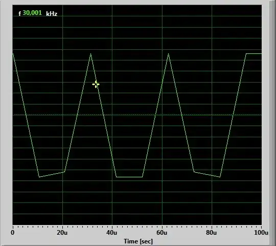
Simple simulation of the above square circuit.

Kenn Sebesta
  • 650
  • 3
  • 13
  • 1
    Please edit your question and elaborate on what Formula SAE is and how it applies to what you're doing - your question just launches into it like everyone knows. I know because I searched the internet but every single reader doesn't want to. The better the quality of your question, the better the quality of the answers you will attract. Thanks. – TonyM Feb 04 '22 at 18:06
  • Thanks for the tip. As you notice, it's readily searchable online. but if it's a cause for hangup or distraction it's probably better just to edit it out. It's utterly irrelevant to the question except to avoid commenters saying "why do you need so many, everyone else uses fewer?" – Kenn Sebesta Feb 04 '22 at 18:11
  • I should add that the sole reason I specify a battery pack is that I could see someone coming from left field to say "they're all even-steven electrically, but this topology one is easier to wire up". This kind of network would also be useful for a massive number of strain gauges, or other resistive sensor. – Kenn Sebesta Feb 04 '22 at 18:15
  • Mmmm, if you're going to downvote, please explain why. Both positive and negative feedback are crucial for building the best SE sites. – Kenn Sebesta Feb 05 '22 at 21:58

3 Answers3

3

A straightforward n*m matrix gives you nm resistors, with n+m leads, and the ability to measure the temperature of every thermistor uniquely, without interaction, without simultaneous equation mathematics in the MCU. It requires n voltage drives switchable between 0 V and some finite voltage, and m current sense channels.

Consider the following 3x4 matrix

schematic

simulate this circuit – Schematic created using CircuitLab

BUF1 drives 5 V, the others drive 0 V. Because of the virtual ground amplifiers, resistors R5 to R12 have no voltage across them, so conduct no current. Only R1 to R4 supply current to the virtual ground amplifiers, which produce a voltage proportional to the current and hence 1/resistance.

Temperature in a battery pack changes fairly slowly, seconds to 10s of seconds, so multiplexing all those thermistors into a normal MCU should present no timing problem.

Obviously buffer outputs are cheaper than ADC inputs, so it might make sense to have a non-square array with perhaps twice as many buffers as virtual ground channels.

I would strongly advise against wiring up a huge battery pack in one go. Break the monitoring down into modules. Consider a small PCB with 2xHC595, two quad packs of opamps, and an 8:1 analogue multiplexer. That would connect back to your MCU/ADC by power, ground, SPI clock, SPI data line, one analogue output, these shared by all your other modules, and one dedicated board enable to write to that particular one. The 595s give you 16 outputs, 3 for analogue channel, one for analogue output enable, and 12 to drive the thermistor buffers, giving you a 12x8 = 96 thermistor module. That feels to me to be about the right size for modularity, or you could add a couple more 595s or delete some of the opamps, play with the dimensions, there is no right size. Replicate the board as often as required to equip all your battery modules.

Neil_UK
  • 158,152
  • 3
  • 173
  • 387
  • Thank you, that's a nice and tidy circuit which I will consider, especially when considering the very nice reduction in microcontroller complexity. However, regarding wiring bundles I fear it still scales poorly when there are hundreds of cells. There is a certain degree of absurdity to compare against a Tesla pack, but if we took that as the reference with ~7k cells, we would, best case, need 83 switches and 83 ADCs. Whereas the square resistor network might need only need 5 of each. – Kenn Sebesta Feb 04 '22 at 18:46
  • With this design, it's worth considering putting an SPI-controlled ADC on the sensing board, as to avoid running long analog wires. Would add one more wire but would probably make working with it much easier. Actually using the latch line on the 595 would probably be also an option, to minimize pin usage on the MCU. Foregoing the analog multiplexer, using an 8-channel ADC like MAX11142 (2$ @100), you get `16 * 8 = 128` channels per seven wires. This actually scales pretty well - for a total of `monitored_cells * 2 / 128 + 5` MCU pins, most of which can be simple GPIOs.... – jaskij Feb 06 '22 at 07:23
  • 595 is also capable of enough output current that you don't really *need* to use those buffers. MAX11142 being SAR those opamps are probably necessary. So you end up with 5 ICs per board (with quad channel opamps). Having a fully-digital solution, with all lines being in a single direction, it is also fairly easy to add buffering for when you're using longer cables. I've picked this particular ADC because it's currently the cheapest available eight channel ADC on Mouser - it might not be particularly well suited to this application. – jaskij Feb 06 '22 at 07:32
  • In case anyone is interested to see it at work, here is the circuit simulated in Falstad: https://tinyurl.com/y8jellle – Kenn Sebesta Mar 14 '22 at 20:58
  • And here it is with non-inverting output, bounded such that it is always between 0V and 3V: https://tinyurl.com/y9ttbc2z – Kenn Sebesta Mar 16 '22 at 23:48
3

Another approach would be to use digital output temperature sensors that can be daisy-chained, for example the TI TMP144

www.ti.com/product/TMP144

enter image description here

these are less than $1 each and have +/-1C accuracy, and all the conversions done for you. This one lets you chain 16 along one serial wire, significantly reducing the number of connections, you may find some that you can daisy-chain further.

No fun of a clever analog design, but probably pretty effective.

Update

A way to achieve Neil's idea with less wiring is to implement his method in a daisy-chain fashion:,

enter image description here

simply cascade D flip flops - something like the SN74LVC1G80 (available in something you can see - SOT23), make a long shift register, and simply clock a single pulse along it, sequentially selecting the thermistors. You need to take care with the clock line to ensure that the edges remain clean and the slew rate adequate, but within a battery pack this should be possible.

Tesla23
  • 2,928
  • 1
  • 3
  • 9
  • That's a clever solution with the UART, and at <$0.50/ea. the price is hard to beat. I had looked up "one-wire" sensors, and those are 10x more expensive. It's not an answer to the applied-theory question about resistor networks, but thanks a lot for putting these on my radar. P.S. As I'm sure you appreciate, I'm still holding out that someone will answer the original question because I'm interested in the root approach. – Kenn Sebesta Feb 05 '22 at 21:29
  • Quick addendum: the TMP144 is an incredibly tiny chip, it's 750um on a side. TI designed it to fit **between** the solder balls on a CPU: https://e2e.ti.com/blogs_/b/analogwire/posts/how-temperature-sensor-size-and-placement-improve-system-reliability-and-performance. – Kenn Sebesta Feb 05 '22 at 22:11
  • That's a bummer if you don't have the assembly capability. I'll have to start to pay more attention to the size of devices - I recently got halfway through a design using a device which was 1mm x 1.5mm with **10** connections, before I realized the prototyping issues. – Tesla23 Feb 05 '22 at 23:06
  • that's a nice follow-up idea you had there. I modeled it in Falstad: https://tinyurl.com/y9xhnser – Kenn Sebesta Mar 14 '22 at 23:16
  • And here is the same idea, but with a non-inverting output, bounded such that it is always between 0V and 5V: https://tinyurl.com/ycx8y6or – Kenn Sebesta Mar 20 '22 at 14:08
0

I helped students in FAE formula races since 2009 and I have seen them struggling with the same issue that you are encountering today. Therefore, rather that addressing your proposed solution (see X-Y problem) which is the proximate problem, please let me state that the ultimate problem is that the rules of the SAE Formula races pose excessive restriction on the students. In the real world, traction batteries, even those that use multiple cells in parallel, use just a handful of temperature sensors, not one sensor per cell. In formula races, when you use multiple cells you need to a) add a fuse to each cell, and b) add a thermistor to most if not all cells.

Let me share a solution that circumvents the need for so many thermistors in the first place, a solution that we reached in collaboration with Formula teams who raced in the past decade. The solution to the ultimate problem is to use single cells of the desired capacity (image a), not multiple cells in parallel (image b). When you do that, you only need N thermistors for N cells in series, and you don't need a fuse for every cell.

Single series string vs cells in parallel

Davide Andrea
  • 16,164
  • 4
  • 33
  • 62
  • 1
    Downvoting this new answer for the same reason I downvoted your prior one. The advice given is founded on mistaken assumptions and is wrong. 1) The pack is not for Formula SAE. 2) SAE provides a useful platinum safety standard for bespoke packs which undergo in situ testing by non-professionals. 3) It is extremely unlikely manufacturers do pack R&D with a miserly number of temp sensors. 4) Single cells of the required chemistry and capacity do not exist in commerce. If they did, our industry would be using them. 5) This resistor network is useful for all resistive sensors, e.g. strain gauges. – Kenn Sebesta Feb 05 '22 at 04:25