I have a 25kHz PWM signal to control LED strip. In order to transfer the current (~1.7A) from PSU (24V) to LEDs (<10 meters) I want to add an LC filter to reduce EMI and RFI. Also, I am planning to use shielded cat 5e cable to suppress anything left after LC filtration.
So, at given params, my load is ~14Ohm. After calculations, I got L=1.26mH C=3.22uF values at Q=0.707 and F=2.5kHz.
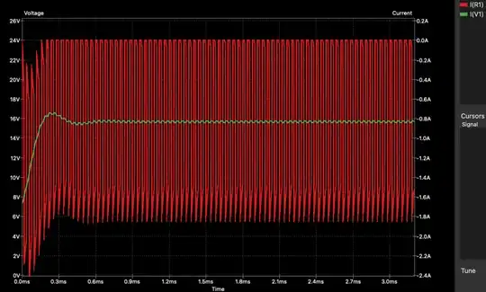
I've simulated the schematic and it works. But I don't really like the spike at the beginning and non-square edges. There is one more thing with it, the induction is too big.
Question 1. How to fix spikes, get square edges and lower the induction? (I know that it is possible to increase frequency, but I would like to keep it at 25kHz)
I've tried to use the following L=126uH C=32.2uF values at F=2.5kHz and R=1.4Ohm. Which leads to Q=7 and as far as I understood here Ripple reduction with LC filter, is ok. Is it ok to use such technique?
Question 2. Do I need some extra components here? Like flyback diode...
