I'm in the process of designing a USB to RS-232 converter for communication with some existing boards, and I ran into two problems.
First Question
I need a way to programmatically reverse the TXD and RXD lines, as there are some boards that are incorrectly wired and need a crossover Serial cable to work.
(instead of pin 2 and pin 3 being RX and TX respectively, the board is wired the other way around)
Since the voltage level of RS-232 is ±3-15V, I was planning to use a DPDT relay and control it using an MCU in order to switch the RX and TX lines.
Question 1: I was wondering if what I'm looking for can be achieved without using relays/SSRS, using passive components. If so, can you please help me with the schematics?
simulate this circuit – Schematic created using CircuitLab
Second Question
An existing USB to RS-232 cable I was using (which had a PL2303TA chip) was fried, when it was connected to these existing boards (since both of the TXD lines were connected to each other). It can still receive data, but the transmit doesn't work anymore.
Question: Is there a way I can prevent the board I'm designing from such a failure?
I feel like in the worst case scenario, one side would output a +15V voltage, while the other one would output a -15V voltage, which would cause driver contention, and is very bad!
Is there a mechanism in order to avoid my chip from being damaged, and prevent the other board's chip from being damaged as well?
Additional Info
As I checked, the manufactured boards have a MAX232 chip on them. I'm also basing my design on a MAX232 chip, if that helps.
I appreciate any tips and general advice!
Update
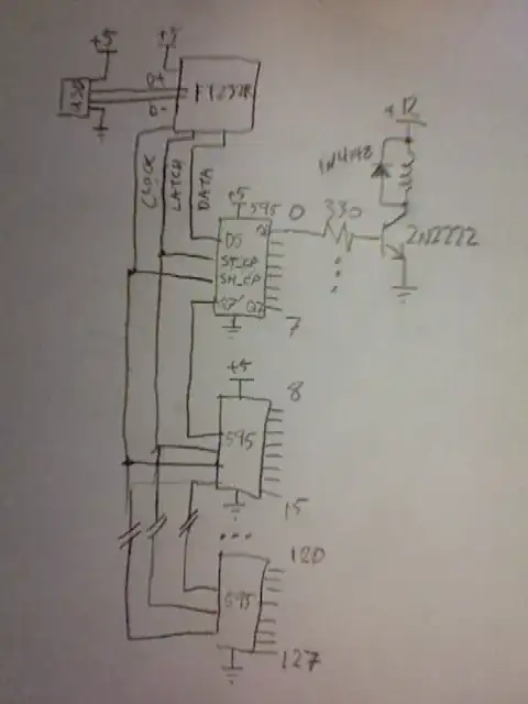
Thank you for all the good advice, the investigation with the PL2303TA chip, explanation of DPDT switching, the idea of multiplexing without a relay, and the use of two chips with separate enable pins! I'm going to use most of the ideas in my design.
I'm also now more confident regarding the issue 2, as the RS-232 specification specifically mentions this wouldn't harm a chip that meets the requirements.
