4

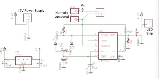
Here is essentially the schematic:

Middle position would be off

I have it mocked up and everything is great, bright and cool to the touch, but one LED array (COBs) is definitely dimmer than the other due to the very small voltage drop .3v across that diode.

Is there a better way to do this?

I already have the single pole switch (obviously a double pole would be better.)

JRE
  • 67,678
  • 8
  • 104
  • 179
Gilligan
  • 57
  • 5
  • 2
    A really simple solution would be to add another diode in series with the leftmost LED. Although, the best solution would be to current limit the two LED's individually. They will most likely start to differentiate at some point, when they wear differently even if they are the same today. – Klas-Kenny Feb 03 '22 at 17:59
  • 2
    Try getting rid of D1 and giving each LED its own series resistor. – vofa Feb 03 '22 at 18:00
  • What does the LED array look like? – jonk Feb 03 '22 at 18:06
  • @vofa D1 serves as a blocking diode so I can run ONE array OR TWO. Without D1 they are just both on all the time. – Gilligan Feb 03 '22 at 18:27
  • @jonk They are 12 V 10 W COBs https://www.amazon.com/photos/shared/qya-tjEOR9eAnP7Wka5dLg.yiKrzonU8ihm1mvR7sUb5u – Gilligan Feb 03 '22 at 18:28
  • 1
    "...everything is great, bright and cool to the touch." Is that 10W resistor cool? Yo don't specify the characteristics of those LED arrays, but in general a dropper resistor is not a great idea efficiency-wise when driving lighting LEDs. You are wasting potentially a lot of power in that resistor. You'd better use some kind of LED driver circuit. Nowadays there are some premade modules that are quite cheap (perhaps less than the 10W resistor). – LorenzoDonati4Ukraine-OnStrike Feb 03 '22 at 18:30
  • @Klas-Kenny, I'm hoping to minimize wear on them with the current limiting. They are 10 watt COBs and I'm going to run them at 6W total circuit so less than 3W each. Keeping their temps low for the sake of not melting anything in the boat as well as them lasting much longer time than if I ran them wide open. – Gilligan Feb 03 '22 at 18:31
  • @LorenzoDonati--Codidact.com sorry, they are 10W panels. Currently have two 5W 5 Ohm resistors in parallel and I'd let a baby touch any of these components. Without the resistors those COBs could almost start a fire (and probably would). – Gilligan Feb 03 '22 at 18:33
  • 1
    Yep! That's why I suggested a LED driver circuit. Some modules let you adjust the current with a trimpot, so you can calibrate the brightness level, and they are very efficient. The only caveat is that the cheap ones are not meant to withstand the salinity conditions of the air in a boat, so no conformal coating or potting. So they might not last long. OTOH, they reduce your battery drain (no power wasted in the resistors), which I assume it might be of some value on a boat. – LorenzoDonati4Ukraine-OnStrike Feb 03 '22 at 18:38
  • I meant one of [these](https://www.amazon.com/Constant-Current-Battery-Charging-Voltage/dp/B077P7WQ1H), for example. I can't vouch for that specific one, since I just searched amazon for the first hit, just to give you an example. That is a 75W-capable module. I've seen less grunty modules at even lower price. – LorenzoDonati4Ukraine-OnStrike Feb 03 '22 at 18:41
  • @Gilligan So they are voltage-driven. That means (to me) that a current-controlled circuit would be *inappropriate* for the devices. Why are you attempting to limit current through resistors? This seems odd, if they really are 12 V systems. I don't see why it would be advisable to place a series resistance in line with a voltage source to a system that requires a low-impedance voltage source for its operation. That would seem to defeat what must have been an internal design expectation by the devices. – jonk Feb 03 '22 at 18:41
  • Are you wanting to avoid the RH LED being dimmer than the left hand LED? Or, are you wanting the left hand LED to be dimmer to match the RH LED. Are you wanting the LEDs all to be the same brightness irrespective of the switch active positions. Be clear about this. Are both LEDs ostensibly identical? – Andy aka Feb 03 '22 at 18:42
  • @LorenzoDonati--Codidact.com we have 520 watts of solar and 490 AH batteries. We rarely have any issues. So the less than 1 watt drain of the resistors isn't going to add up to much. One of this will be going in the bathroom/shower so upping the humidity factor! – Gilligan Feb 03 '22 at 18:43
  • @Andyaka Yes, I'd like them to be the same brightness when the switch has them both on. – Gilligan Feb 03 '22 at 19:06

3 Answers3

3

schematic

simulate this circuit – Schematic created using CircuitLab

You'll need two separate resistors for D2. This will also split your load current up so you won't need the 10W resistor.

vir
  • 14,718
  • 13
  • 28
  • So R2 would be less than R1 and D3 would take some of the load as to "match" them. I'm at 2.2 ohms now... so not a lot of flexibility in choice of resistors. – Gilligan Feb 03 '22 at 18:26
  • You can always mix and match multiple resistors to get to the desired resistance. You could also put diodes in where R1 and R3 are and resistors downstream of the LEDs. – vir Feb 03 '22 at 18:31
  • but we are talking about 5w and 10w resistors... this starts to get pricey doing this. ;) – Gilligan Feb 03 '22 at 18:34
  • If you're running the panels at low power, you'll have less current. Splitting the single resistor up so that each panel gets one will also reduce the heat generated in each device. Maybe 5 and 10W resistors are pricey, but 2 and 3W ones not so much. – vir Feb 03 '22 at 18:52
  • I'm just being overly conscious of heat since it will go in a small lighting fixture in a small space overhead. – Gilligan Feb 03 '22 at 19:09
2

This will equalize the brightness of the LEDs assuming that the LEDs are identical: -

enter image description here

Two added diodes in red circles. All three diodes should be identical and heat-sinked together.

Andy aka
  • 434,556
  • 28
  • 351
  • 777
  • Technically I could scrap the bottom right one because when only one LED array is on you won't be able to really tell it's a bit brighter than when they are both on. – Gilligan Feb 03 '22 at 19:08
  • 1
    @Gilligan that's up to you of course. I thought I'd leave you with that option. – Andy aka Feb 03 '22 at 19:09
  • 1
    ... keeping in mind that the assumption that two LEDs are identical is not always true! – Scott Seidman Feb 03 '22 at 19:33
  • @ScottSeidman, it's a COB with about 100 LED's per array... so I'm sure they average out. Just tried this solution and it's working a treat! Technically my energy consumption came down .05 amps as well. Might be shoddy soldering work as I'm just doing some point to point work right now. – Gilligan Feb 03 '22 at 20:47
2

This is effectively the same as Andy aka's circuit but arranged in a more obvious way.

schematic

simulate this circuit – Schematic created using CircuitLab

Bruce Abbott
  • 55,540
  • 1
  • 47
  • 89