2

I'm not experienced but I don't mind burning stuff to get through, here I'm looking to find out why it's not working.

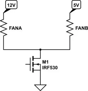
I've got a 5V fan being switched on/off by a mosfet on a board I didn't made. The 5V fan GND is plugged into FAN1 (-). I want to add a 12V fan and I wanted it to be switched at the same time as the 5V fan.

Therefore I put the 5V GND and the 12V GND tied together plugged into the FAN1 (-)

The 12V fan get his 12V supply from a buck converter. The 5V fan get his 5V supply from the board itself.

But the result is that the 12V fan is spinning up when the load is OFF (the 5V fan is still off as it should be). I stopped there the experiment.

Can I put 2 grounds of different voltage tied up together on a single mosfet switching on/off the load? According to my experiment, the answer seems no, why?

Is there a solution or would it be necessary to have one mosfet per different voltage?

enter image description here

Unknown
  • 23
  • 3
  • 1
    Can you draw a schematic or block diagram? Your terminology is unclear. – DKNguyen Feb 02 '22 at 16:07
  • @DKNguyen I edited the post with more data and a schematic from the pcb I'm using, hopefully that will help. – Unknown Feb 02 '22 at 16:19
  • Do you mean that the grounds are tied together? "Grounds in parallel" isn't clear. There's no reason tying grounds of different supplies together should be a problem, but there are lots of other things that could be a problem that we can't guess at without a schematic and more details. – John D Feb 02 '22 at 16:19
  • @JohnD Yes that's what I meant, I edited my post with the schematic if that can help – Unknown Feb 02 '22 at 16:22
  • 3
    To save your audience severe headaches and neck muscle injury please [draw schematics with inputs at left, loads at right, positive voltages at top and grounds at bottom](https://electronics.stackexchange.com/q/28251/2191) - Uninjured engineers might provide quicker and better answers! – RedGrittyBrick Feb 02 '22 at 16:28

1 Answers1

5

You mean like this?

schematic

simulate this circuit – Schematic created using CircuitLab

There are problems if you open the switch. The 12V will back flow into the 5V.

The reason your test had the 12V fan running slowly was due to this current flowing from the 12V into the 5V. The 12V fan was behaving as if 12V-5V = 7V was applied to it. The motor driver in the fan has parasitic diodes that are anti-parallel to the entire driver which allows a sneak path for current to flow in reverse and bypass everything else in the fan which is why the 5V fan did not react.It would have appeared as a diode conducting current around the fan in the reverse direction.

You can put a diode in series with the 5V fan to prevent this.

DKNguyen
  • 54,733
  • 4
  • 67
  • 153
  • I'd worry about leakage through the fans pulling the 5V supply up when the FETs are off, since they generally can't sink current. – John D Feb 02 '22 at 16:25
  • 1
    @JohnD Yes, I just realized that and edited. – DKNguyen Feb 02 '22 at 16:25
  • @DKNguyen OK I get it, any solution to prevent the current going backwards? – Unknown Feb 02 '22 at 16:26
  • 1
    @Unknown Diodes for each fan. Or namely, the 5V fan. – DKNguyen Feb 02 '22 at 16:26
  • @DKNguyen OK I think I understand, and why the 12V fan was spinning a bit when the switch is closed? – Unknown Feb 02 '22 at 16:39
  • @Unknown Switch closed typically means conducting. Do you mean not conducting? If so, that was from 12V back flowing through to 5V through the fan as if you applied 7V. Fan motor drivers have internal antiparallel diodes that provides a sneak path around the driver in reverse so the 5V fan would have appeared as a diode passing current backwards through it and not reacted. – DKNguyen Feb 02 '22 at 16:40
  • @DKNguyen Ah! Yes I mean not conducting. – Unknown Feb 02 '22 at 16:44
  • 1
    @Unknown - If you put a diode in series with each of the fans that will avoid the reverse flow and allow it to function as you wish. – Kevin White Feb 02 '22 at 18:39
  • 1
    @TonyM Okay......... – DKNguyen Feb 02 '22 at 18:57