1

This is a peak detector taken from page 21 of the opamp ADA4610: enter image description here
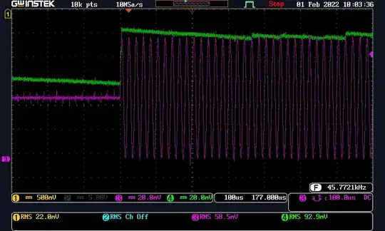
I need it to capture peaks from 500KHz sine wave. I can't understand why when the sine starts it goes above the peak and then discharge with a costant (I think determined by C5*R3). Look at the screen below: purple track is VI in the schematic and the green one is VO. VI is a 500KHz unipolar sinewave with 200mVpp, R3=10k

enter image description here

Here is the same test with C5=470nF, R3=10k:

enter image description here

Same test at 50kHz with C5=47nF, R3=10k and Vipp=400mV:

enter image description here

50kHz with C5=470nF, R3=10k and Vipp=100mV:

enter image description here

Somehow it seems the system is underdamped, but adding a compensation cap across D1 does not solve it. Could someone help me to fix this?

DATASHEETS:
AD8066, SMS3924

kristian_
  • 31
  • 5

2 Answers2

1

It looks to me like the problem is that negative feedback comes from the 2nd op-amp hence, there will be a greater overshoot than if one op-amp were used: -

enter image description here

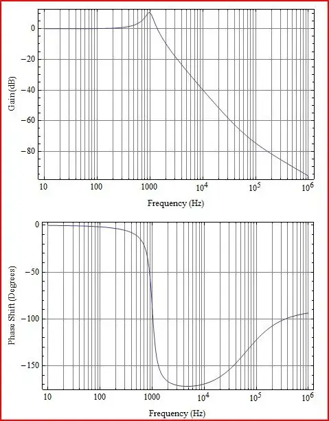
So, U1B's output is going to be kind-of "open-loop" for input transients until Vout has stabilized somewhat and provided negative feedback to suppress that output transient on U1B. Apart from anything else, the AD8066 does naturally produce overshoot on its output: -

enter image description here

A perfect storm of an op-amp that produces a bit of overshoot and negative feedback coming from a 2nd stage op-amp. With C5 made 470 nF it probably damps the overshoot down so the displayed peak on the oscilloscope looks OK.

If I were you I'd do two things: -

  • Look at the voltage on pin 7 of U1B to see the true op-amp overshoot of the first stage
  • Set up a simulation to mimic wat you see and mess around with values until you get a fix
  • Apply the fix to your real hardware.
Andy aka
  • 434,556
  • 28
  • 351
  • 777
  • Looking at the waforms on pin 7 is something like a high peak at the point the sine starts and then goes like sine but with no DC average – kristian_ Feb 02 '22 at 12:01
  • Yes @kristian_ that's what I'd expect to happen. – Andy aka Feb 02 '22 at 12:03
  • So you'd suggest to play with R3 and C5 in oder to attenuate the overshoot? – kristian_ Feb 02 '22 at 14:37
  • Probably not. I might be tempted to put a resistor in series with D3 then, where that takes me after that is down to what the simulation is indicating. – Andy aka Feb 02 '22 at 14:40
0

Bandwidth gain product is only 15 MHz for this OpAmp. I think you are pushing the limit of what this OpAmp can do. In the datasheet capacitor in the middle, C5, is 1 uf, and in your example it is much smaller.

Your options are to reduce the middle capacitor further, to increase the bandwidth by making the circuit even more unstable and noisy, or to take an OpAmp with higher bandwidth gain product, or to use transistors because OpAmps for multi MHz range can be expensive.

  • Thanks for the answer. I'm using AD8066, not ADA4610. How to evaluate its bandwidth in this application? – kristian_ Feb 02 '22 at 11:05
  • @kristian_ that one has bandwidth gain product of about 100 MHz, it should be enough. Required value for your application would be about 100 times larger than the frequency you work with, 500 kHz. So, about 50 MHz is likely enough. It can be estimated from frequency analysis of the signal you want to produce. Or roughly estimated from the time of the shortest event - in your case it is the signal rise time that is the shortest event, about 100 times shorter than the 500 kHz signal you work with. – Surprised Seagull Feb 02 '22 at 11:15
  • So the overshoot is not due to GBP limitation, am I right? – kristian_ Feb 02 '22 at 11:22
  • Yes. GBP is not an issie I think. Overshoot and feedback can be a problem at lower frequencies too. I agree with Andy. – Surprised Seagull Feb 02 '22 at 11:24