2

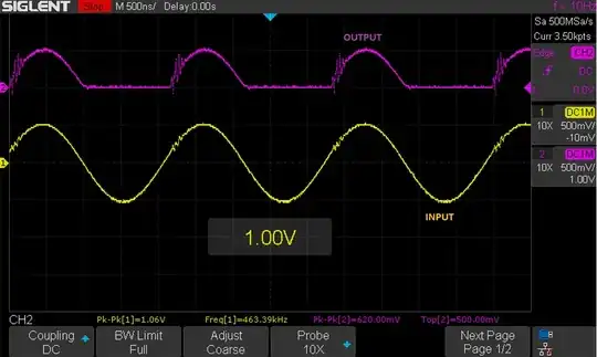
I have used a voltage follower with a TSH082. I was able to get a half-wave signal with some slight ringing on the output (shown below).

Is there a way to reduce the ringing on the half-wave signal output?

Single Supply Voltage follower

enter image description here Signal Measurement

Single Supply inverting amplifier:

enter image description here enter image description here

I have used a precision rectifier, and I unable to get a half wave signal.
Using a single supply precision half wave rectifier: enter image description here

Null
  • 7,448
  • 17
  • 36
  • 48
Sam
  • 319
  • 1
  • 8
  • Does your circuit use a bypass capacitor on the power supply? – qrk Jan 31 '22 at 23:35
  • @qrk it has a bypass capacitor of 0.1uF between the +5V to GND. – Sam Feb 01 '22 at 00:09
  • 1
    What is your system objective - rectification at high speed is difficult. Are you intending to get amplitude? Or is it specially for wave-shaping? There may be other ways to achieve your objective. – Kevin White Feb 01 '22 at 00:41
  • @KevinWhite I want to get a half wave signal of the input. – Sam Feb 01 '22 at 00:43
  • 1
    @Sam - yes, but why? What is the system objective. Maybe that is achievable without getting the half-wave rectified version. It is rare to need a half-wave rectified signal. Are you trying to get the average amplitude of the signal for example? – Kevin White Feb 01 '22 at 01:17
  • @Sam - do you mean the instantaneous amplitude or the average amplitude? Are you going to filter the signal after the rectification then compare? – Kevin White Feb 01 '22 at 02:46
  • @KevinWhite the main reason: I have two branches, where one branch is constant amplitude sine wave and the other branch is varying. When I do differential of two branch, the moment the varying branch amplitude is lower than the other constant amplitude branch, the output signal inverts which I don't want. Therefore, the idea is to only take the halfwave signal of both branches, and do differential. Hope this makes sense. – Sam Feb 01 '22 at 03:06
  • @KevinWhite i think its instantaneous amplitude; just to be sure, its given Voltage peak at that moment. – Sam Feb 01 '22 at 03:31
  • @Sam - what is supposed to happen on the negative half-cycle? – Kevin White Feb 01 '22 at 09:32
  • It doesn't seem like you need a rectifier at all - just a comparator and multiplexer. – Kevin White Feb 01 '22 at 15:33
  • @KevinWhite can I possible talk to you virtually. In differential amplifier, when the branch with constant amplitude is higher than the varying branch, the output of the differential branch inverts; I want to avoid that. I only want an output when the varying amplitude branch is higher than the constant amplitude branch. – Sam Feb 01 '22 at 17:00
  • Let us [continue this discussion in chat](https://chat.stackexchange.com/rooms/133715/discussion-between-kevin-white-and-sam). – Kevin White Feb 01 '22 at 18:26

1 Answers1

3

It looks like you are driving the outputs to create a half-wave rectification in an unstable manner.

This Op Amp has GBW = 100 MHz with 40 deg phase margin when loaded with 150 ohms// 30 pF yet your results are different.

Assertion: This design is a poor method of rectification for high speed.

This is what happens when the output saturates and the input is no longer a virtual ground or an error amplifier with a null input operating in the linear region. Effectively the gain is always 0 when the output is saturated then the input approaches the null input and the non-linear gain goes to near 80 dB of linear gain open loop with unity gain closed loop.

  • Diode saturation capacitance and reverse recovery time also influence the results and thus keeping C in the low pF and reducing R without current limiting will help.

Essentially the Op Amp has less phase margin coming out of saturation.

Recommendation:

  • Use a bipolar supply or bias the output to keep the inputs & outputs active in the linear range. (see schematic below)
  • use an analog switch and comparator to rectify the signal.
  • try a suitable pull-up resistor on the output to pre-bias the output current.
  • try a 150 ohm load to dampen the response of the high side driver

enter image description here

enter image description here

and YET another Design enter image description here

Tony Stewart EE75
  • 1
  • 3
  • 54
  • 182
  • I want to let you know that I have tried the above circuit design before but it did not work out. is there a specific type of diode that we need to use for precision half wave rectifier? I will try the circuit again with TSH82, and post the result. Thank you – Sam Feb 01 '22 at 00:21
  • The lowest capacitance small signal diodes and check impedance ratio at slew rate – Tony Stewart EE75 Feb 01 '22 at 00:31
  • I have tried both the circuitry, and I am unable to get half wave rectifier; I have uploaded the signal in the post, and added few more info. I can get a half wave signal using a non-inverting amplifier or inverting amplifier with slight ringing; would that help with stability. – Sam Feb 01 '22 at 03:04