6

I have faced this problem many times that I connects Relay with pic microcontroller and whenever I put Load on Relay's Contacts PIC16f877a resets. I some time solve this problem by triggering another relay from basic relay attached to PIC. But this is not a solution. Can any one describes Why pic is affected with this relay spark. And what is really happening which causes pic to reset. Following things I have kept in mind while building circuit

  • I have 1K Pullup resistor on pin 1 (Reset pin) of Pic 16f877a
  • Fuses are, Power up timer = enable, Brown out detect = enable, LVP= disable, CP=enable
  • Power supply is filtered, ceramic capacitor of value .1uf connect across both ends of regulator
  • Crystal is 4MHz, and 33pf capacitor across crystal are close to (Circuit works fine, problem of reset occurs only when relay turns on with Load connected)
  • Relay is used of 12v/5amp ratings
  • C945 NPN Transistor is used to drive the relay
  • Reverse biase 1N4148 diode is connected across relay coil to save reverse leakeage

I never faces such problem in Atmel 89c51 microcontroller with same relay interfacing circuit. It is PIC who goes reset every time. But if do not connect any load to relay the circuit works fine. No reset occurs. Can any-one describes what is the issue with PIC?

Here is schematic, Crystal is attached as mentioned above enter image description here

Abdul Rehman
  • 419
  • 1
  • 5
  • 15
  • 3
    1. A schematic helps visualize what has been implemented, far better than a series of textual bullet points. 2. Replace the 1n4148 with a Schottky barrier diode like the 1n5819. 3. Try putting a capacitor (try 10 uF) across the diode. – Anindo Ghosh Mar 12 '13 at 11:08
  • 1
    I have had this problem before. It was because of the *collapsing* on the power supply. Put a 10 uF capacitor on the Vdd power rail, and most probably your problem will be solved. Also, to avoid SR latch-up, as @Kaz noted, Microchip suggest an RCR network. Look for this information in the datasheet of your microcontroller. – abdullah kahraman Mar 12 '13 at 11:23
  • Grounding: does your load's return current share paths with your small signal digital world? – Kaz Mar 12 '13 at 11:50
  • @Kaz... well, Load is 220V, thus definitely separate AC power source is given. Line from Relay and neutral directly to AC inductive load. With 2 Amp current Load. I added diode for reverse leakage prevention. – Abdul Rehman Mar 12 '13 at 11:59
  • @abdullahkahraman...... yes 10uf capacitor reduces the amount of rapid reset. Thanks. Pic reset is very common problem i faced. I really want to know any technical details why it is happening. As if i built same interfacing circuitry with ATmel 89c51 every thing goes fine. I am really surprised why PIC have problem? – Abdul Rehman Mar 12 '13 at 12:06
  • @anindoGosh I am going to try schottky barrier, but some how i did not understand the logic of schottky here? Will you please explain a lit. As schottky is costly comparatively and Later I am want to attach 20 relays. I am sorry if this question looks silly. – Abdul Rehman Mar 12 '13 at 12:09
  • 1
    @AbdulRehman Try increasing the capacitor to 100uF. For the replacement on 1N4148, search for "Flyback diode". About grounding.. Every cable/trace has a resistance, but very small. However, with sufficient current, there can be a voltage drop. This means the ground will be at a higher potential than 0 volts. – abdullah kahraman Mar 12 '13 at 12:41
  • 1
    @AbdulRehman While several excellent inputs have been provided already, hence my prior comment may be irrelevant, my suggestion for a Schottky comes from trying to alleviate flyback pulses from the relay coil at the source. Typical flyback energy can require 1 to several amps of pulse current capability in the diode, 4148 doesn't manage that. Also, the lower the diode voltage, the earlier in the pulse the bypass begins. Finally, between the Schottky and the capacitor, the impulse absorption would be more robust. A flyback diode as others suggested is really what you need there. – Anindo Ghosh Mar 12 '13 at 16:37

2 Answers2

13

This kind of symptom is to be expected from a number of bad design practises, including bad grounding, bad decoupling, bad power supply filtering, and bad layout.

Bad Grounding

You didn't say much about this, which means you didn't think much about grounding and it is therefore a possible problem. Just connecting everything to a ground net would be fine if nothing has any ground current. Of course various parts do. This current times the impedance back to the one point you get to call ground causes a offset voltage. Don't just think of ground in terms of DC. DC is the easy part. Consider the series inductance of any connection and then the high frequency ground return currents that run accross that connection.

What is the relay switching? Where does the current it is switching run? Is the relay switch side completely isolated from the coil, or do they share a common ground? If the latter, the substantial currents when the relay switches on its load could be causing ground bounce at the micro or other parts of the system.

Bad Decoupling

This is clearly a problem in your case. You put 100 nF caps on both sides of the regulator, but you completely forgot to put bypass caps accross the PIC power and ground pins. This can cause power glitches local to the PIC when it switches internally, and can cause local ground glitches when those current transients travel along the ground net back to somewhere they can finally loop back to the supply.

Bad Power Supply Filtering

You at least seem to have thought about this, but then only implemented it partially. 100 nF if pretty skimpy, particularly for the input of the regulator. I like to put 10 µF at the input of a regulator, maybe with 100 nF additional accross it for extra high frequency filtering. However, nowadays 1 and 10 µF ceramic caps are cheap and available, and have better properties than the 100 nF leaded caps of ancient times where that value originated. So unless you really are stuck in a time warp, don't use 100 nF except for special cases.

You mention nothing about bulk power supply filtering, so this is another problem. Where does the relay power come from? If after the regulator, then are you sure the regulator can supply the total power current with the relay on? Could the relay be powered from before the regulator? That would be better to keep the regulated supply clean, but may not be appropriate if the unregulated supply voltage is too unpredictable.

Add a 10 µF ceramic cap close to the input of the regulator, then a larger electrolytic cap at the power supply feed point.

Bad Layout

Just connecting everything to what it's supposed to be connected to isn't good enough. You have to think about where the currents will be flowing and what that may result in. In particular, think of the high frequency loop currents caused by all digital circuits including your PIC. The larger the loops, the more will be radiated. Since reception and transmission capabilities of antennas are symmetric, the same circuit that radiates a lot of crap will likewise pick up crap from the environment. Especially when ground and bypassing were done poorly, the received crap can cause significant voltages and thereby erroneous operation. This is where bypassing helps again. The PIC is a current source at high frequencies. The bypass cap shunts those currents to a small local loop which minimizes radiation, and at the same time minimizes susceptibility to external radiation.

Other problems

You mention a transistor being used to drive the relay, but didn't mention a base resistor. No base resistor will cause excessive current to be drawn from the PIC pin with resetting a plausible enough result, especially without a bypass cap and now bulk capacitance on the supply.

To make more concrete recommendations, show a complete schematic and your laout. I think the problems will be evident enough then.

Added in response to schematic

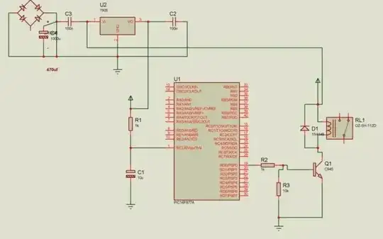
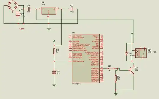
  1. The output of the full wave bridge and input to U2 is totally messed up. The capacitor (can't read the designator, how come you couldn't see that?) is shorted, which also shorts the output of the full wave bridge. C3 blocks DC into the regulator. C3 should be between the regulator input and ground, and should be 10 µF or so ceramic as I said above. 100 nF is really small for this purpose.
  2. There is no power connection to the PIC. How can this possibly run?
  3. There are no bypass caps accross the PIC power, even if it was hooked up.
  4. Without a external oscillator or crystal, you have to be using the internal oscillator. Make sure that is enabled. I don't remember if the '877A even has a internal oscillator. I know the '877 didn't, but maybe that was added for the A version.
  5. What's with the arrow sticking up from the top of the relay connection?
  6. 10 µF is very large for being on MCLR, and a bad idea. There is no need for that cap. Get rid of C1 altogether and change R1 to 10-20 kΩ. 1 kΩ is rather low for a programmer or debugger to overcome.
Olin Lathrop
  • 310,974
  • 36
  • 428
  • 915
  • Your answer really helps me a lot. I am reading and reading it again. It really clears many more concepts. I have added schematic that I mostly uses for my PIC circuitry – Abdul Rehman Mar 12 '13 at 15:44
  • 1
    The schematic was build in proteous, ofcourse power supply and external 4MHz Crystal is added, I did not mention it here because I supposed it was understood that minimum circuitry is added to run pic properly, Yes even 877 do not have internal crystal. This was simulation diagram pointing toward those circuitry that most people mention can cause problem. Arrow denotes the +ve power connection in proteous above the relay – Abdul Rehman Mar 13 '13 at 12:27
  • 3
    @Abdul: No, nothing is understood unless you explicitly show it. We don't know what you know an what you don't. Not showing us details we are supposed to assume you included is wasting the time of those trying to give you free help. – Olin Lathrop Mar 13 '13 at 13:34
2

add a snubber pair across the relay contact..

Durairaj
  • 21
  • 1