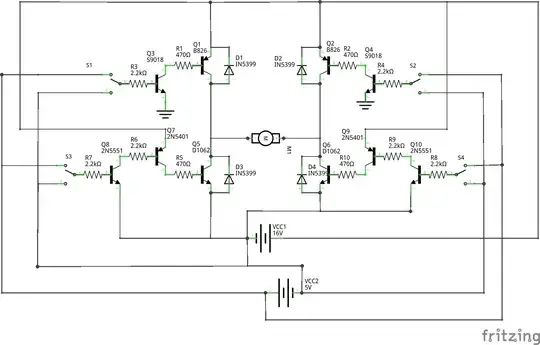
It appears as though the wipers are unwired in this schematic. Are only the far left and far right pins wired in this circuit?
-
3Looks like a simplification by the designer. As you say, it makes no sense with a pot and not connect the wiper. – winny Jan 31 '22 at 12:19
-
4I suppose it means that this is a trimmer with one end and wiper connected (a 2k resistor that can be fine tuned to exact value) – Jiří Maier Jan 31 '22 at 12:25
-
2These are rheostats, not potentiometers. Same component, just connect the wiper to the bottom end. – Jan 31 '22 at 14:17
-
Thank you very much. So I should be "tied" to the idea that the arrow extending outward is the actual symbol of the wiper of the resistor, but should rather just realize holistically this is the symbol for the variable resistor, in this case, wired as a rheostat. Is that right? – David Graham Feb 01 '22 at 09:34
2 Answers
This style of showing a potentiometer as a user-variable resistor goes back decades, at least to the 1960s.
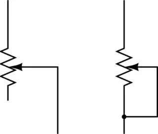
There are two ways of connecting a pot' to achieve this, as shown below.
The wiper-only connection does the job. Some applications suit the 'wiper and end' connection, some don't. If the wiper fails over time or becomes dirty, both real possibilities, the wiper/end circuit will still give the full pot' resistance because the ends are still connected. The advantage is that the circuit will still have a resistance in it. The disadvantage is that it may hide the wiper failure. So it's for the designer to select the appropriate one.
Note that a potentiometer connected like this resembles a rheostat. However, rheostat typically describes a adjustable resistance for passing higher currents for main loads. Pots' are typically used for passing signal currents, to dissipate little power in the part itself. In general, rheostat part ranges have much higher max. power ratings and lower max. resistance than potentiometer part ranges. Here, your 2K potentiometers are changing the adjustment voltage for the regulators, they're not part of the current path to the output load.

simulate this circuit – Schematic created using CircuitLab
- 21,742
- 4
- 39
- 62
-
The configuration on the right is typically called the 'rheostat' configuration. It is quite common. Wikipedia: "The most common way to vary the resistance in a circuit continuously is to use a rheostat.[6] It is basically used to adjust magnitude of current in a circuit by changing length. The word rheostat was coined about 1845 by Sir Charles Wheatstone..." – Chris Knudsen Jan 31 '22 at 13:01
You use two of the terminals, the wiper and one end. The wiper can (and should) be tied to the unused end (there are only advantages in doing so).
In this case I would use the wiper and the CCW end, with the CW end tied to the wiper.
The reasoning behind this is that I would like to have the output voltage increase with clockwise rotation of the pot shaft. That requires that the resistance increase with clockwise rotation in this particular case.
(of course if the pot is nonlinear, such as audio taper, the two ends are not interchangeable for that reason alone)
Image from Wikipedia with added annotations:
You can check this with a multimeter set to an appropriate resistance range on the chosen terminals.
Also, if you are creating schematics it helps to have the CW an CCW terminals on the pot explicitly shown on the schematic symbol and to use a symbol that shows the (usual) three pot connections.
In rare cases you might run into rheostats that have only two terminals. For example, in very old cars the dashboard lighting was sometimes controlled by a power rheostat. In that case, the resistance decreased with clockwise rotation so that the incandescent lamps would burn brighter.
- 376,485
- 21
- 320
- 842
-
1Thanks! That's great advice about labeling the CW and CCW rotations of the pot. I got a little confused last time wiring one because I had the concept right when I was thinking about building the last prototype I made, and then I flipped it upside physically but didn't flip it upside mentally along with the board, and I ended up wiring the pot backward to how I wanted it to rotate. Oops! Your tip will help a lot! – David Graham Feb 01 '22 at 09:32


