1

enter image description hereI have a project to design a 3 stage amplifier using BJT transistors. I have most of the design requirements satisfied except for the output voltage swing. I'm at a loss as to how I can increase this. From what I understand the swing shown in the screenshot below is at +/- 3V, and the design requires +/- 5V.

Any recommendations on how I could increase the output swing or improve the design in general would be much appreciated.

Thanks! 3 Stage BJT Amplifier: CE -> CE -> CC

donkong
  • 29
  • 3
  • What ***are*** the design constraints? What I see is ridiculously high resistor values used to bias the 1st stage (which I don't believe will be what you really want) and an emitter follower at the output, which is also likely not a good idea. So I would appreciate seeing the details you've been provided. (Not so much a schematic you claim gets you close.) – jonk Jan 29 '22 at 21:11
  • 1
    I'll add a pic of the design constraints – donkong Jan 29 '22 at 22:48
  • Have you learned about bootstrapping? Do you know how to use high gain and then global NFB to control the gain and reduce distortion? Also, where does it say three stages? – jonk Jan 29 '22 at 22:56
  • I haven't learned about bootstrapping beyond reading the link that another user posted in the comments. No I don't know how to do that. It says to use 3 stages in an earlier portion. – donkong Jan 29 '22 at 23:11
  • What about global negative feedback? Know anything about that? (Sorry about delays, on occasion, but I'm busy elsewhere as well -- new exterior hydrant design.) – jonk Jan 29 '22 at 23:49
  • Nah, I've heard other folks mention it being used as a more sophisticated design, but I haven't learned about it. No worries mate, just nice to have someone to bounce ideas off of. – donkong Jan 30 '22 at 00:19
  • Well, you won't get an output impedance of 500 Ohms with a 10k emitter follower resistor (for one half of a cycle, anyway.) So that's out. You will probably want to break up the gain evenly into at least the first two stages (assuming you want to keep the emitter follower and use a smaller emitter resistor.) I've no particular idea how well you can keep to 90-110 gain over wide temperature range and device types without using NFB. It is what I'd want if I were stuck on a tight voltage gain like that. – jonk Jan 30 '22 at 03:04
  • @donkong I added some information to my earlier answer, have a look and see if it helps. – GodJihyo Jan 30 '22 at 06:46
  • You should look at this for the methodology and what you should "own" ... https://electronics.stackexchange.com/questions/601240/designing-a-multi-stage-circuit – Antonio51 Jan 30 '22 at 15:29
  • @donkong How many transistors are you limited to? Can you use 2 BJTs in a stage? – jonk Jan 31 '22 at 02:37

2 Answers2

3

R1 is too high a value.

The output stage, Q3, is configured as an emitter follower. It can only source current not sink current. The only current driving the output negative is the current in R1. That is why the output waveform is asymmetric.

I would reduce R1 so that it is much lower than the output load. Say 2.2k.

You could also replace R1 with a current source from the negative rail, that would improve output swing further.

You also don't really need to bias the output stage. You could DC couple Q3 base to the collector of Q2. For best output swing the collector of Q2 should be about ground.

Kevin White
  • 32,097
  • 1
  • 47
  • 74
  • LTspice simulation sez - DC couple Q2 to Q3 (remove C4, R2, R3). Change R1 to 2.2k, R6 to 2.7meg, R7 to 220k, R5 to 26k. Remove C8. Combine R4 and R8 to a single 2k resistor. – Bruce Abbott Jan 30 '22 at 09:50
1

The output of this circuit doesn't look bad until the input is above around 20 mV, then the first stage starts to clip. You're going to have to look at the biasing starting with the first stage, and you may want to look at using feedback to control the gain, reduce distortion and improve the bandwidth.

The resistor values for the first stage bias are rather high, if you are trying to keep the input impedance high you might look at using bootstrapping.

Additional:
Now that you posted the requirements I took another look at it and I have a working simulation that I believe meets them. As this appears to be schoolwork I'm not going to just post it but rather give you some direction on a design method.
You have a maximum current draw and number of stages, so start there. You need to divide that current among the stages so get a rough idea of how much each one should get. They don't need to be evenly divided.
Once you've got that you need to figure out how much gain you want for each stage to get to the required total gain.
Then you have the required output voltage and impedance. Start with your final stage, and get it working. Feed a signal directly into it that will drive it to the desired output and bias it to get the current, output voltage and impedance you need.
Once you get that working, connect the stage before it and feed the signal to that, reducing it to account for the stage gain. Figure out the collector and emitter resistances you need to get the gain and current while keeping the output offset centered for maximum swing. Get that working and then add the first stage and do the same with it, this time keeping in mind the input impedance as well.
Check to see if it meets all the requirements and adjust as necessary. If you need to know how to check input and output impedance leave a comment and I will explain that.
Also note, I did not need to use bootstrapping or feedback to get it working. It could possibly be improved with them but you shouldn't need them to meet the design constraints.
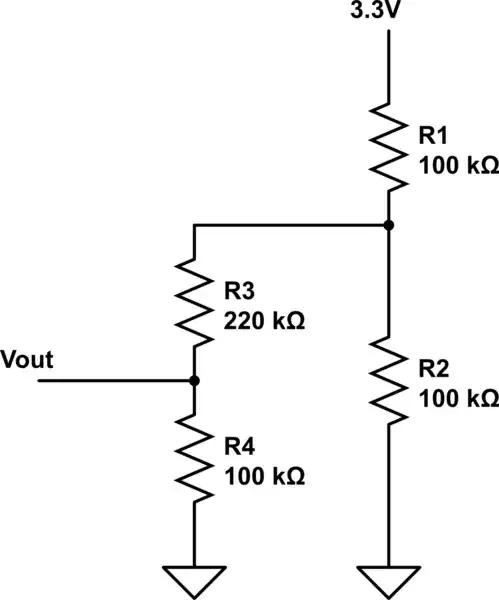
GodJihyo
  • 17,628
  • 1
  • 16
  • 45