0

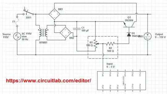
Is it possible to control high current with small rms voltage?

UPDATE

Do you think that this is gonna work?

enter image description here

clabacchio
  • 13,481
  • 4
  • 40
  • 80
InGeek
  • 103
  • 2
  • Do you want to control ON/OFF switching or more like dimming a lightbulb? – jippie Mar 12 '13 at 07:20
  • it maybe a lights or an AC motor – InGeek Mar 12 '13 at 08:46
  • any ideas? I didnt test it, but I bought all the parts – InGeek Mar 12 '13 at 18:32
  • 1
    What is the goal of this circuit? Dim a lightbulb or electroshock therapy? (good question, immensely bad circuit!) – jippie Mar 12 '13 at 19:00
  • I got it from one of 1995 russian journal :), – InGeek Mar 12 '13 at 19:04
  • Not sure if it will work at all, but if you build it with Arduino, your entire PC will be live as there is no galvanic separation. Wait a moment for more details. – jippie Mar 12 '13 at 19:06
  • As several people pointed out, mains power is potentially extremely dangerous. Yes we use it every day all around the house, but that is only possible because extreme care has been taken to prevent the electric power from being touched. The circuit diagram you propose here has a transformer in it, but it is not providing any galvanic separation. This in turn means that the entire ciruit is directly attached to mains. Now the thing turns really bad because you want to control the circuit through an Arduino and Arduino is attached to your PC. – jippie Mar 12 '13 at 19:25
  • 1
    This means that literally *everything* somehow attached to your PC now carries the mains voltage. Devices like mouse and keyboard are not designed to withstand these voltages. If your PC enclosure is properly grounded most probably the household mains fuse will blow (and that is probably the best thing that can happen!). – jippie Mar 12 '13 at 19:27
  • Electronics as a hobby is entirely fun, but you have to play it by its rules. In this case use optocouplers to interface between Arduino and mains. – jippie Mar 12 '13 at 19:31
  • @jippie Alright, I got it, thanks for providing with this information. – InGeek Mar 12 '13 at 21:18

3 Answers3

2

First a word of warning: Please respect the 110V mains supply, it can be lethal.

Dimming of a lightbulb works like: Dimmer to bulb control

The below two links describe a method with a zero crossing circuit and a triac to control a lightbulb from Arduino (or most any microcontroller). The controller is synchronized to the mains supply by a zero crossing detector and in turn fires the triac at sooner or later, resulting in dimming the lightbulb.

Here is a project that explains a project to make just that with an Arduino. http://www.instructables.com/id/Arduino-controlled-light-dimmer-The-circuit/step2/Arduino-controlled-light-dimmer-The-software/

Luckily this hardware is also readily built available, here is an example: http://www.inmojo.com/store/inmojo-market/item/digital-ac-dimmer-module/

jippie
  • 33,033
  • 16
  • 93
  • 160
1

You can control a solid-state relay with a microcontroller output. And if you need more current than that, the solid-state relay can control a bigger non-solid-state relay.

Be careful if you really don't know what you are doing, you can hurt or kill someone with 110 VAC.

markrages
  • 19,905
  • 7
  • 59
  • 96
-3

Ya use a interfacing circuit between the low voltage circuit and high voltage circuit. Interfacing may contain an isolator and some transistor or darlington pair( if you want to increase current )

Santosh
  • 161
  • 2
  • 10